 Facebook
 Google
 GitHub
 Linkedin
Hello
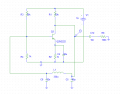
I have a pierce oscillator (bjt)
I use cap 22n , 90p , l=330u
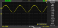
so I have to get f=923khz
but I get 836khz on scope what is the reason
and also when I use low amount of inductor 56u for example no oscillation occur
thanks
I have a pierce oscillator (bjt)
I use cap 22n , 90p , l=330u
so I have to get f=923khz
but I get 836khz on scope what is the reason
and also when I use low amount of inductor 56u for example no oscillation occur
thanks
Attachments
-
 9.1 KB Views: 58
 -
 20 KB Views: 59
Last edited:
")


