Facebook
 Google
 GitHub
 Linkedin

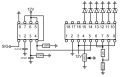
I'm trying to build a circuit to display engine speed as a bar of 6 LEDs using an LM2907 and LM3914. I'd like first LED to illuminate at 8000rpm and for all LEDs to be lit at 13000rpm.
I've found a few example circuits (including those in the datasheets) which I can tell are what I need, but I'm having trouble picking the correct resistor and capacitor values for the chips to give me the range I want. So far I've got values of 33.3kR, 29nF and 73nF for R1, C1 and C2 on the LM2907 using the application notes pdf. The capacitor values aren't standard, so I'd like to know how I can change them to get a range from the LM2907 suitable for the 3914.
The supply voltage can be either 5V or 12V.