PIC16F88 problem controlling hbridge

Thread Starter

aGpLT

Joined Jan 21, 2010
128
OK, there's a problem.

Does your 12v in measure 12v? If so, figure out why your C5 and C6 are not measuring >10v.

Dog-gonit. Just realized that in order to charge C5, VT1 must be OFF, and VT2 must be ON.
In order to charge C6, VT3 must be OFF and VT4 must be ON. Otherwise, there is no path to ground to charge the caps; simply raising SD won't charge them.

However, the way you have the HIN/LIN wired, you don't have independent control of the LINs - which is what I was referring to earlier on in the thread. :/

In order to charge the high-side boost caps, you will have to momentarily flip RB0 and RB1. This will be hard on the motor.
Heh it's so funny that i want to cry :( If i understand right you advice me to HIN/LIN control separately, uh 4 ports... :x

About 12V yeah its 12v... :) when i measure between supply GND and VB it show 12V :) about capacitors i don't have any idea :x

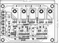
here is pcb (C8 and C7) they are 100nF ceramic, and in parallel with C6 and C5 connected 2 capacitors 100nF as you said before :)
 

Attachments

SgtWookie

Joined Jul 17, 2007
22,230
Yes. Keep the HIN/LIN for each side separate.

If you really don't want to use 5 I/O pins (four for HIN/LIN, one for SD), you could use a 74HC595 shift register and a single I/O pin to crank in and store the data.

Roman Black's page explains how to do this:
http://www.romanblack.com/shift1.htm

But, you are using a Basic language that only supports time increments of 1mS. A work-around could be devised, but that would involve performing loop testing and some means of accurately measuring elapsed time.
 

Thread Starter

aGpLT

Joined Jan 21, 2010
128
Thanks, firstly i will try with 5 pins :) to see if it works...
But still what about VB/VS ? why only 6.5V ? i don't get it at all :x they are connected good, without mistakes, but somehow i lost so much voltage.

MSpause var byte ' Milliseconds between charging caps, suggest 10 to 50, even numbers
Ctr var byte ' Used in loop for 50% pwm
RunCt var byte ' Used in loop
LeftHIN var PORTB.0 ' left HIN
SD VAR PORTB.1
LeftLIN VAR PORTB.2 ' left LIN
RightHIN VAR PORTB.3 ' right HIN
RightLIN var PORTB.4 ' right LIN

ANSEL = %00000000 ' All pins changed from analogue to digital
OSCCON = $60 ' Internal clock setted to 4Mhz
TRISB = %00000000 ' All PORTB pins are outputs.
' ---------------------------------------------------------------
High SD ' Turn off MOSFET drivers and charge boost caps C5/C6
MSpause = 50 ' 50 millisecond pause
Pause MSpause ' wait a bit
Loop:
High LeftHIN
LOW LeftLIN
LOW RightHIN
HIGH RightLIN
For RunCt = 1 to 200 ' We're going to loop 200 times, so run time will be MSpause * RunCt = 10 seconds
Low SD ' Turn on MOSFET drivers
Pause (MSpause-2) ' wait a bit...
High SD ' Turn off MOSFET drivers...
Pause 2 ' ...and charge MOSFET caps for 2mS
Next RunCt

' At this point, the IR2110 drivers are disabled, and the caps have charged for at least 2mS.

Pause 1000 ' One second pause.
goto Loop
END
Is it okay ? i tryed it but still nothing new...
 
Last edited:

Thread Starter

aGpLT

Joined Jan 21, 2010
128
One man told me, that Low side transistors works good, but they need to work some time for HIGH side transistors to open. Transistors must always change state. its so hard to understand all these things... but its harder to write program...
 
Last edited:

SgtWookie

Joined Jul 17, 2007
22,230
Look, I've told you before that this is a strictly G-rated forum. Keep your language clean. I really don't want to have to say it again.

I don't know why you put SD in the middle of the HINs/LINs. I would've used RB0-RB3 for the HINs/LINs and RB4 (or even a different port) for SD.

That way you could simply shove a char or byte in Port B to set all the bits the way you want at once.

Try it like this:
Rich (BB code):
MSpause  var byte    ' Milliseconds between charging caps, suggest 10 to 50, even numbers 
Ctr      var byte    ' Used in loop for 50% pwm
RunCt    var byte    ' Used in loop
LeftHIN  var PORTB.0 ' left HIN
SD       VAR PORTB.1
LeftLIN  VAR PORTB.2 ' left LIN 
RightHIN VAR PORTB.3 ' right HIN
RightLIN var PORTB.4 ' right LIN

ANSEL = %00000000 ' All pins changed from analogue to digital
OSCCON = $60      ' Internal clock setted to 4Mhz
TRISB = %00000000 ' All PORTB pins are outputs. 
' ---------------------------------------------------------------
       High SD ' Turn off MOSFET drivers
       MSpause = 50 ' 50 millisecond pause

Loop:
       For RunCt = 1 to 200 ' We're going to loop 200 times, so run time will be MSpause * RunCt = 10 seconds
	  ' Set up to re-charge caps
          Low LeftHIN
          High LeftLIN
          Low  RightHIN
          High RightLIN
          Low SD ' Turn on MOSFET drivers
          Pause 1 ' ...Charge caps for 1mS
          High SD ' Turn off MOSFET drivers...
          Pause 1 ' ...Pause 1mS to ensure no shoot-thru
          ' Set up gate drivers to turn the motor left.
          High LeftHIN
          Low  LeftLIN
          Low  RightHIN
          High RightLIN
          Low SD ' Turn on MOSFET drivers
          Pause (MSpause-3) ' wait a bit...
          High SD ' Turn off MOSFET drivers...
          Pause 1 ' ...Pause 1mS to ensure no shoot-thru
       Next RunCt

       Low LeftHIN
       High LeftLIN
       Low SD ' Turn on MOSFET drivers

       ' At this point, both low side MOSFETs are on, and the high side are off; the caps will charge for 1 sec.
       Pause 1000 ' One second pause.
       High SD ' Turn off MOSFET drivers...
       Pause 1 ' ...Pause 1mS to ensure no shoot-thru
       goto Loop
END
 

Thread Starter

aGpLT

Joined Jan 21, 2010
128
Look, I've told you before that this is a strictly G-rated forum. Keep your language clean. I really don't want to have to say it again.

I don't know why you put SD in the middle of the HINs/LINs. I would've used RB0-RB3 for the HINs/LINs and RB4 (or even a different port) for SD.

That way you could simply shove a char or byte in Port B to set all the bits the way you want at once.

Try it like this:
Rich (BB code):
MSpause  var byte    ' Milliseconds between charging caps, suggest 10 to 50, even numbers 
Ctr      var byte    ' Used in loop for 50% pwm
RunCt    var byte    ' Used in loop
LeftHIN  var PORTB.0 ' left HIN
SD       VAR PORTB.1
LeftLIN  VAR PORTB.2 ' left LIN 
RightHIN VAR PORTB.3 ' right HIN
RightLIN var PORTB.4 ' right LIN

ANSEL = %00000000 ' All pins changed from analogue to digital
OSCCON = $60      ' Internal clock setted to 4Mhz
TRISB = %00000000 ' All PORTB pins are outputs. 
' ---------------------------------------------------------------
       High SD ' Turn off MOSFET drivers
       MSpause = 50 ' 50 millisecond pause

Loop:
       For RunCt = 1 to 200 ' We're going to loop 200 times, so run time will be MSpause * RunCt = 10 seconds
      ' Set up to re-charge caps
          Low LeftHIN
          High LeftLIN
          Low  RightHIN
          High RightLIN
          Low SD ' Turn on MOSFET drivers
          Pause 1 ' ...Charge caps for 1mS
          High SD ' Turn off MOSFET drivers...
          Pause 1 ' ...Pause 1mS to ensure no shoot-thru
          ' Set up gate drivers to turn the motor left.
          High LeftHIN
          Low  LeftLIN
          Low  RightHIN
          High RightLIN
          Low SD ' Turn on MOSFET drivers
          Pause (MSpause-3) ' wait a bit...
          High SD ' Turn off MOSFET drivers...
          Pause 1 ' ...Pause 1mS to ensure no shoot-thru
       Next RunCt

       Low LeftHIN
       High LeftLIN
       Low SD ' Turn on MOSFET drivers

       ' At this point, both low side MOSFETs are on, and the high side are off; the caps will charge for 1 sec.
       Pause 1000 ' One second pause.
       High SD ' Turn off MOSFET drivers...
       Pause 1 ' ...Pause 1mS to ensure no shoot-thru
       goto Loop
END
Sorry about my language. Sometimes it happens, its not intentionally. I tryed this one and still nothing. About SD now it doesn't matter but i will change it after my controller will work :)
 

Thread Starter

aGpLT

Joined Jan 21, 2010
128
Ok so lets think a little. One left low side MOSFET must be high left high side MOSFET low. at start right low side MOSFET must be high for certain time (T-t), when i close right low side MOSFET and open right high side MOSFET for time (t). if i want 10kHz PWM so my T = 100us. Pulse width % = t/T*100.

Rich (BB code):
MSpause  var byte    ' Milliseconds between charging caps, suggest 10 to 50, even numbers 
Ctr      var byte    ' Used in loop for 50% pwm
RunCt    var byte    ' Used in loop
LeftHIN  var PORTB.0 ' left HIN
SD       VAR PORTB.1
LeftLIN  VAR PORTB.2 ' left LIN 
RightHIN VAR PORTB.3 ' right HIN
RightLIN var PORTB.4 ' right LIN

ANSEL = %00000000 ' All pins changed from analogue to digital
OSCCON = $60      ' Internal clock setted to 4Mhz
TRISB = %00000000 ' All PORTB pins are outputs. 
' ---------------------------------------------------------------
       High SD ' Turn off MOSFET drivers
       MSpause = 50 ' 50 millisecond pause

Loop:
       For RunCt = 1 to 200 ' We're going to loop 200 times, so run time will be MSpause * RunCt = 10 seconds
      ' Set up to re-charge caps
          Low LeftHIN
          High LeftLIN
          Low SD ' Turn on MOSFET drivers
          Pause 1 ' ...Charge caps for 1mS
          High SD ' Turn off MOSFET drivers...
          Pause 1 ' ...Pause 1mS to ensure no shoot-thru
          ' Set up gate drivers to turn the motor left.
          High LeftLIN
          Low  LeftHIN
          High RightLIN
          Pause 40
          Low  RightLIN
          HIGH RightHIN
          PAUSE 60
          LOW RightHIN 
          Low SD ' Turn on MOSFET drivers
          Pause (MSpause-3) ' wait a bit...
          High SD ' Turn off MOSFET drivers...
          Pause 1 ' ...Pause 1mS to ensure no shoot-thru
       Next RunCt

       ' At this point, the IR2110 drivers are disabled, and the caps will need to be re-charged.
       Pause 1000 ' One second pause.
       goto Loop
END
i think its this way, but still don't work :) And could you say why i get 5V between VS and VB but not >10V ?
 
Last edited:

SgtWookie

Joined Jul 17, 2007
22,230
OK, you need to figure out WHY C5 and C6 are not charging to >10v.

It should not be that difficult.

As long as the high-side MOSFETs are turned OFF, and the low-side MOSFETs are turned ON, C5/C6 should charge to >10v.

If they do not, something is wrong from where your 12V supply comes in, through the Schottky diodes that charge them, to the connection of the low sides of C5/C6 to the drains of the low-side MOSFETs, or from the source terminals of the low-side MOSFETs to ground.

Figure out what is wrong.
 

Thread Starter

aGpLT

Joined Jan 21, 2010
128
I tryed new program and measured Vgs:
VT1 - 6.2V
VT2 - 3V
VT3 - 0V
VT4 - 0V

measured between capacitors C5 and C6 , got 12V it seems that the main problem here is program, bus still motor dont rotate :(
MSpause var byte ' Milliseconds between charging caps, suggest 10 to 50, even numbers
Ctr var byte ' Used in loop for 50% pwm
RunCt var byte ' Used in loop
LeftHIN var PORTB.0 ' left HIN
SD VAR PORTB.1
LeftLIN VAR PORTB.2 ' left LIN
RightHIN VAR PORTB.3 ' right HIN
RightLIN var PORTB.4 ' right LIN

ANSEL = %00000000 ' All pins changed from analogue to digital
OSCCON = $60 ' Internal clock setted to 4Mhz
TRISB = %00000000 ' All PORTB pins are outputs.
' ---------------------------------------------------------------
High SD ' Turn off MOSFET drivers
MSpause = 50 ' 50 millisecond pause
LOW SD
High LeftLIN
Low LeftHIN
right:
High RightLIN
PauseUS 30
Low RightLIN
HIGH RightHIN
PAUSEUS 70
LOW RightHIN
goto right
END
I measured LOAD pins, 3.6V both :/
 
Last edited:

SgtWookie

Joined Jul 17, 2007
22,230
So, PauseUS is a valid instruction? And it pauses for microseconds instead of milliseconds?

You're turning on the drivers before you've set up the ports. Bad news.
 

Thread Starter

aGpLT

Joined Jan 21, 2010
128
So, PauseUS is a valid instruction? And it pauses for microseconds instead of milliseconds?

You're turning on the drivers before you've set up the ports. Bad news.
Yeah its valid and for uS.

MSpause var byte ' Milliseconds between charging caps, suggest 10 to 50, even numbers
LeftHIN var PORTB.0 ' left HIN
SD VAR PORTB.1
LeftLIN VAR PORTB.2 ' left LIN
RightHIN VAR PORTB.3 ' right HIN
RightLIN var PORTB.4 ' right LIN

ANSEL = %00000000 ' All pins changed from analogue to digital
OSCCON = $60 ' Internal clock setted to 4Mhz
TRISB = %00000000 ' All PORTB pins are outputs.
' ---------------------------------------------------------------
High SD ' Turn off MOSFET drivers
High LeftLIN
Low LeftHIN
LOW RightLin
LOW RIghtHIN
MSpause = 50 ' 50 millisecond pause
LOW SD
right:
High RightLIN
PauseUS 30
Low RightLIN
HIGH RightHIN
PAUSEUS 70
LOW RightHIN
goto right
END
I corrected program but still nothing :/ boostcaps charges to 12V measured it several times.
 
Last edited:

SgtWookie

Joined Jul 17, 2007
22,230
After all of this fooling around, you've probably blown your MOSFETs and/or the IR2110's.

It would only take a few moments to fry your MOSFETs if you had both the high and low side on simultaneously.

You need to be more careful about what state your bridge is in before you start enabling it willy-nilly.

The very first thing you should do when your code starts executing is to raise SD to make sure all of the MOSFETs are off.

Then you can start setting up to charge the capacitors by turning both low-side MOSFETs on, and both high-side MOSFETs off.

Then wait 100uS or so.
Then lower SD.
Then wait a millisecond or so.
Then raise SD.
Then wait 100uS or so.

Then set up for your motor rotation. If you're going to try rotating the motor right, then leave the left bridge alone, turn off the right low-side MOSFET, and turn on the right high-side MOSFET.
Then lower SD.
here:
Let it run for 200uS or so.
Then turn off the right high-side MOSFET, and wait for it to turn off.
Then turn ON the right low-side MOSFET, and wait for it to turn ON and charge the cap.
Then turn OFF the right low-side MOSFET, and wait for it to turn off.
Then turn ON the right high-side MOSFET.
GOTO here:
 

Thread Starter

aGpLT

Joined Jan 21, 2010
128
Ok i tested all MOSFETS two of four was dead. I changed them. hot to test IR2110 i don't so i had few extra of them and changed.
 
Last edited:

SgtWookie

Joined Jul 17, 2007
22,230
OK now, remember what I wrote in my last post.

You need to start calculating out what the propagation delay through the IR2110 will be, and the charge/discharge time for the MOSFET gates, and also look at the MOSFET turn-on/turn-off times in the datasheet.

If you don't calculate all this stuff out, and put appropriate delays in your program in ALL of the necessary places, you will again wind up with sauteed MOSFETs.

Err on the side of caution. If you don't, Murphy will smite your MOSFETs.
 

Thread Starter

aGpLT

Joined Jan 21, 2010
128
OK now, remember what I wrote in my last post.

You need to start calculating out what the propagation delay through the IR2110 will be, and the charge/discharge time for the MOSFET gates, and also look at the MOSFET turn-on/turn-off times in the datasheet.

If you don't calculate all this stuff out, and put appropriate delays in your program in ALL of the necessary places, you will again wind up with sauteed MOSFETs.

Err on the side of caution. If you don't, Murphy will smite your MOSFETs.
Its really out of my league... i have one week to do all project... :| Okay, so when i Shut Down IR2110 it takes

tsd+toff+tfall=290ns

need to w8 some time for all MOSFETS to turn off so =

(tdoff+t_f)*4=284ns

after i know that all mosfets are down i need to set 2 low MOSFETS on and 2 others off for capacitors to charge.

(tdon+tr)*2=112ns, (tdoff+tf)*2=142ns

and w8 some time to charge capacitor (dunno how long.). when i need to turn off one low side MOSFET 71ns..... cmon i think i am writing nonsenses, as i said its out of my league. :(

Maybe i should use another driver ? because this one isn't best choose for DC motors, and maybe it would be much faster than trying to make this one to work. Just i need to make it work somehow and as fast as i can...
 
Last edited:
Top