
 Facebook
 Google
 GitHub
 Linkedin
Heh it's so funny that i want to cryOK, there's a problem.
Does your 12v in measure 12v? If so, figure out why your C5 and C6 are not measuring >10v.
Dog-gonit. Just realized that in order to charge C5, VT1 must be OFF, and VT2 must be ON.
In order to charge C6, VT3 must be OFF and VT4 must be ON. Otherwise, there is no path to ground to charge the caps; simply raising SD won't charge them.
However, the way you have the HIN/LIN wired, you don't have independent control of the LINs - which is what I was referring to earlier on in the thread. :/
In order to charge the high-side boost caps, you will have to momentarily flip RB0 and RB1. This will be hard on the motor.
 If i understand right you advice me to HIN/LIN control separately, uh 4 ports... :x
 About 12V yeah its 12v...
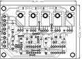
when i measure between supply GND and VB it show 12V about capacitors i don't have any idea :xhere is pcb (C8 and C7) they are 100nF ceramic, and in parallel with C6 and C5 connected 2 capacitors 100nF as you said before
Attachments
-
 80.9 KB Views: 21





