PIC16F877A interface 4x4keypad 2x16LCD

Thread Starter

BlissEva

Joined Jun 28, 2015
20
Hello
As far as I can see, the resistors R1, R2, R3 and R4 are not connected as Pull-Up or Pull-Down. They are in series with the inputs of the PIC.
To be pull-up, they must be connected From the PIN to VCC.
To be Pull-Down, they must be connected From the PIN to GND.
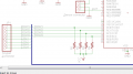
ok. you mean i have to connect every resistor which is connected to keypad with Vcc and Ground? is it like this?
 

Attachments

Thread Starter

BlissEva

Joined Jun 28, 2015
20
I am waitng for the TS to reply as to their purpose. I agree with @MrCarlos ; they are NOT pull up nor down resistors. Likely they are included for a circuit that needs it's input pins protected. They are unnecessary in this circuit. As a matter of fact, if their value is too large, the micro will not be able to determine a reliable level.

It is on the column inputs, that pull up resistors are needed. The keypad will present a floating input most if the time, making reads of the key press unreliable.
i have already connect them to Vcc and gnd but not sure is it the connection is right. can hep me check?
 

Attachments

absf

Joined Dec 29, 2010
1,968
Looking at your software, the resistors should be on C1-C4. Check also the TRISC direction register and see if it is defined correctly.

Allen
 

ErnieM

Joined Apr 24, 2011
8,415
i have already connect them to Vcc and gnd but not sure is it the connection is right. can hep me check?
Yes that looks perfect. RC0 thru RC3 are the button sense inputs, and you want them to be pulled high when no button is pressed.

I do have to ammend "perfect" because I do not know the details of your keypad so I am assuming how it works. You can check the electrical operation by simply removing the PIC, connect COL1 to ground, and see if the corrosponding row buttons are the only ones to pull down the row lines. Note you don't need a program, just a DVM (or a LED and a resistor).

If you can't remove the PIC you could either write a test program to make the COL outputs as inputs and manually connect ground, or a program that makes just one COL low. The program need not be anything fancy, just something quick and dirty to proove a point then tossed away.
 

MrCarlos

Joined Jan 2, 2010
400
Hello BlissEva
.
Looking at the code that you enclose in your post #1 reads as follows:
#define R1 RC0 // Row1 Port C BIT 0
#define R2 RC1 // Row2 Port C BIT 1
#define R3 RC2 // Row3 Port C BIT 2
#define R4 RC3 // Row4 Port C BIT 3
#define C1 RC4 // Column1 Port C BIT 4
#define C2 RC5 // Column2 Port C BIT 5
#define C3 RC6 // Column3 Port C BIT 6
#define C4 RC7 // Column4 Port C BIT 7
.
In Function Main says:
TRISC = 0xF0; // KeyPad. So, BITs 0, 1, 2 And 3 Are Outputs. BITs 4, 5, 6 And 7 Are Inputs.
.
Subsequently, through the rows, you shift a low level(0) and verify which column is low (0) to make a decision.
Now analyze the circuit is in the PDF document attached to you.
Your design should be working . . . Or not ??
 

Attachments

atferrari

Joined Jan 6, 2004
5,012
Can't he run a simulator?
I did when creating my keyboard read routine in Assembler. With some ingenuity, I tested it and never had to look back.
EDIT to add:

Divide and conquer. Test one at a time.
//EDIT
 

Thread Starter

BlissEva

Joined Jun 28, 2015
20
Hello BlissEva
.
Looking at the code that you enclose in your post #1 reads as follows:
#define R1 RC0 // Row1 Port C BIT 0
#define R2 RC1 // Row2 Port C BIT 1
#define R3 RC2 // Row3 Port C BIT 2
#define R4 RC3 // Row4 Port C BIT 3
#define C1 RC4 // Column1 Port C BIT 4
#define C2 RC5 // Column2 Port C BIT 5
#define C3 RC6 // Column3 Port C BIT 6
#define C4 RC7 // Column4 Port C BIT 7
.
In Function Main says:
TRISC = 0xF0; // KeyPad. So, BITs 0, 1, 2 And 3 Are Outputs. BITs 4, 5, 6 And 7 Are Inputs.
.
Subsequently, through the rows, you shift a low level(0) and verify which column is low (0) to make a decision.
Now analyze the circuit is in the PDF document attached to you.
Your design should be working . . . Or not ??
yes. but i think i had found the error, im not connecting my resistor to the Vcc. i have already make my PCB, what can i do to reconnect the resistor to Vcc?
 
Last edited:

Thread Starter

BlissEva

Joined Jun 28, 2015
20
Can't he run a simulator?
I did when creating my keyboard read routine in Assembler. With some ingenuity, I tested it and never had to look back.
EDIT to add:

Divide and conquer. Test one at a time.
//EDIT
sorry can i know what is divide and conquer?
and can i know what if my resistors do not connect with the Vcc? can them works?
 

MrCarlos

Joined Jan 2, 2010
400
Hello BlissEva
.
Probably Your (MPLab HiTechC With IDE compiler) has the instruction:
port_c_pullups (1);// Pull-Up Resistor's In Port C, in all BITs in Port C.
And also: If the controller, You Are Using (PIC16F877P), Support Internal Pull-Up Resistors.
1Means YES Put It. 0 means No.
If Yes You do not need external resistors
.
Otherwise you have to modify the PCB.
Or jumpers placed instead resistors,
Then:
The resistors placed vertically.
And
The upper terminals, of the resistors, connected to Vcc.
.
Note: Check data sheets of the controller to see if it is possible to use internal resistors.
You can find the data sheets on the following link:
http://www.alldatasheet.com/
Ask in Part Name: PIC16F877P
 

ErnieM

Joined Apr 24, 2011
8,415
sorry can i know what is divide and conquer?
"Divide and conquer" is a general phrase meaning you split a big problem into smaller simple problems and solve each in turn.

can i know what if my resistors do not connect with the Vcc? can them works?
I do not see how this will work without pull up resistors, but you can probably add them to your PCB, especially if you use a DIP for the PIC or JP1 uses 0.1" center holes: it is simple to lap solder down one end of some 0805 resistors to these pads, then join the other ends with a jumper that runs off to Vcc.

I did check the data sheet for the PIC16F877A and it does not have internal pull up resistors on Port C. It may be possible that some other PIC in the same package has such but I am unaware of this or how you would find it, other than to ask on Microchip's own forums.
 

ErnieM

Joined Apr 24, 2011
8,415
Put them on whatever side goes to the PIC inputs. they need to be there so a button not pressed will leave the input high. Only buttons both selected and pressed make an input low.

I can't say row or column as either can be wired as the inputs, plus on the iPad I am using tonight I can't see your schematic.
 

djsfantasi

Joined Apr 11, 2010
9,237
hi, i should put the resistor in column or row? what the different?
As myself, absf, and MrCarlos have pointed out, the resistors belong on the column pins, in a pull up configuration.

Why? Because the input pins must never be left "floating" or not connected to anything.
 

Thread Starter

BlissEva

Joined Jun 28, 2015
20
Yes that looks perfect. RC0 thru RC3 are the button sense inputs, and you want them to be pulled high when no button is pressed.

I do have to ammend "perfect" because I do not know the details of your keypad so I am assuming how it works. You can check the electrical operation by simply removing the PIC, connect COL1 to ground, and see if the corrosponding row buttons are the only ones to pull down the row lines. Note you don't need a program, just a DVM (or a LED and a resistor).

If you can't remove the PIC you could either write a test program to make the COL outputs as inputs and manually connect ground, or a program that makes just one COL low. The program need not be anything fancy, just something quick and dirty to proove a point then tossed away.
btw i had followed what you taught me, use a LED to test my keypad. but why the LED turn off when i press the button and light up when it is not been pressed?
 

ErnieM

Joined Apr 24, 2011
8,415
btw i had followed what you taught me, use a LED to test my keypad. but why the LED turn off when i press the button and light up when it is not been pressed?
That is as it should be. You have a pull up resistor which turns the LED on.

When you push the button you ground that point which turns the LED off.
 
Top