PIC16F877A interface 4x4keypad 2x16LCD

Thread Starter

BlissEva

Joined Jun 28, 2015
20
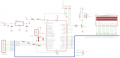
can anyone help me to find out what is the problem of the code? It is successfully built but cant show the number of keypad when i press. I'm using MPLab IDE with HiTechC compiler.


Code:
#include <htc.h>
#include <pic.h>
#include <stdio.h>

__CONFIG(0x3F72)

#define RS RD2        //LCD
#define EN RD3
#define D4 RD4
#define D5 RD5
#define D6 RD6
#define D7 RD7

#define R1 RC0        //Row1
#define R2 RC1        //Row2
#define R3 RC2        //Row3
#define R4 RC3        //Row4
#define C1 RC4        //Column1
#define C2 RC5        //Column2
#define C3 RC6        //Column3
#define C4 RC7        //Column4

#define kyp_PORT          PORTC
#define kyp_PORT_Dir    TRISC

#define FOSC
#define BAUD_RATE 9.6
#define BAUD_VAL (char)(FOSC/(16*BAUD_RATE))-1;

#define _XTAL_FREQ 8000000        //set the crystal oscillator frquency
#include "lcd.h"
                         
void main(){

    TRISD = 0x00;        //LCD
    TRISC = 0xF0;        //keypad
 
     EN = 1; 
    OPTION_REG &= 0x7F;

    lcd_init();
    lcd_clear();
    void keypad_init();
    char keypad_read();
    char keypad_wait();             
    char key_get;
    __delay_ms(100);

      while(1){ 
        lcd_cmd(0x00);
        lcd_cmd(0x01);

        __delay_ms(5);
        SetCursor(1,0);
        WriteString("Enter: ");
        __delay_ms(5);
        SetCursor(2,0); 
        for(int j=0;j<17;j++){
            key_get = keypad_wait();
            WriteChar(key_get);
        }     
    }
}

char keypad_read(void){
 
    R1 = 0;        //Row1
    R2 = 1;
    R3 = 1;
    R4 = 1;
    __delay_us(30);
    if(C1 == 0){ return '1';}
    if(C2 == 0){ return '2';}
    if(C3 == 0){ return '3';}
    if(C4 == 0){ return 'A';}

    R1 = 1;        //Row2
    R2 = 0;
    R3 = 1;
    R4 = 1;
    __delay_us(30);
    if(C1 == 0){ return '4';}
    if(C2 == 0){ return '5';}
    if(C3 == 0){ return '6';}
    if(C4 == 0){ return 'B';}

    R1 = 1;        //Row3
    R2 = 1;
    R3 = 0;
    R4 = 1;
    __delay_us(30);
    if(C1 == 0){ return '7';}
    if(C2 == 0){ return '8';}
    if(C3 == 0){ return '9';}
    if(C4 == 0){ return 'C';}

    R1 = 1;        //Row4
    R2 = 1;
    R3 = 1;
    R4 = 0;
    __delay_us(30);
    if(C1 == 0){ return '*';}
    if(C2 == 0){ return '0';}
    if(C3 == 0){ return '#';}
    if(C4 == 0){ return 'D';}

    return 0xFF;
}

char keypad_wait(){
    char pressed_key = 0xFF;

    do{
        pressed_key = keypad_read();
    }
    while (pressed_key == 0xFF);

    while (keypad_read() != 0xFF);

    return pressed_key;
}

void kyp_init(){
    TRISC = 0x00;
    PORTC = 0xFF;
    kyp_PORT = 0x00;
    kyp_PORT_Dir = 0xF0;
    OPTION_REG = 0x7F;
    __delay_ms(30);
}
 

ErnieM

Joined Apr 24, 2011
8,415
Does anything appear on the display?

What steps have you tried?

Did you try using an in circuit debugger to watch the code flow?
 

GopherT

Joined Nov 23, 2012
8,009
there are just too many possible problems to address without fully troubleshooting the keypad, the circuit that detects a key-press, the connections to the LCD, your chip programmer, and on and on and on.

Could you tell us what does work in your circuit. What test programs you have written and proven that each piece of the system does work mechanically and design-wise and the only possible issue could be the programming. Then we can discuss the program.

Cheers.
 

Thread Starter

BlissEva

Joined Jun 28, 2015
20
Does anything appear on the display?

What steps have you tried?

Did you try using an in circuit debugger to watch the code flow?
hi, my LCD can show the word "Enter" that i wrote in the main program but cannot show anything when i press my keypad.
i never try any circuit debugger.
 

Thread Starter

BlissEva

Joined Jun 28, 2015
20
there are just too many possible problems to address without fully troubleshooting the keypad, the circuit that detects a key-press, the connections to the LCD, your chip programmer, and on and on and on.

Could you tell us what does work in your circuit. What test programs you have written and proven that each piece of the system does work mechanically and design-wise and the only possible issue could be the programming. Then we can discuss the program.

Cheers.
hi, my LCD can show what i wrote in the main but cant show the keypad value when i pressed. im new to this so i not really understand how to test my program.
 

ErnieM

Joined Apr 24, 2011
8,415
Do you have a schematic to post?

What programmer do you have? Is it a PICkit? (They do in circuit debugging.)

What other equipment do you have? Voltmeter? Oscilloscope?
 

ErnieM

Joined Apr 24, 2011
8,415
The PICkit 2 is also an in circuit debugger, and you seem to have it connected on dedicated pins so you can use it along with everything else on your board.

I am not sure how you get the Hitech C to work in MPLAB with the debugger but start by looking at the menu to do a debug build, then the menu for the debugger where you can choose you PICkit.

Worst case you might have to upgrade to the free XC8 compiler,which is bases on the Hitech one so most of the code remains the same.
 

djsfantasi

Joined Apr 11, 2010
9,237
Are you sure that TRISC is defined correctly? It appears to me that your rows are defined as outputs and your columns as inputs... The opposite from the way you use them.
 

ErnieM

Joined Apr 24, 2011
8,415
The rows are on the low nibble, the cols are on the high nibble.

Rows are driven, cols are read.

TRISC or key_Port_dir is loaded with 0xF0 which makes rows on outputs, cols on inputs, which looks correct to me.
 

djsfantasi

Joined Apr 11, 2010
9,237
The rows are on the low nibble, the cols are on the high nibble.

Rows are driven, cols are read.

TRISC or key_Port_dir is loaded with 0xF0 which makes rows on outputs, cols on inputs, which looks correct to me.
The rows are on the low nibble, the cols are on the high nibble.

Rows are driven, cols are read.

TRISC or key_Port_dir is loaded with 0xF0 which makes rows on outputs, cols on inputs, which looks correct to me.
Ok. Sorry. I think I confused the bit numbering. Should have sketched it out before answering.
 

ErnieM

Joined Apr 24, 2011
8,415
I agree the code is confusing as things get declared at the very top and at the very bottom of the code, but it does appear to be correct.
 

Thread Starter

BlissEva

Joined Jun 28, 2015
20
The PICkit 2 is also an in circuit debugger, and you seem to have it connected on dedicated pins so you can use it along with everything else on your board.

I am not sure how you get the Hitech C to work in MPLAB with the debugger but start by looking at the menu to do a debug build, then the menu for the debugger where you can choose you PICkit.

Worst case you might have to upgrade to the free XC8 compiler,which is bases on the Hitech one so most of the code remains the same.

actually what the different between XC8 compiler and Hitech?
 

djsfantasi

Joined Apr 11, 2010
9,237
When no key is pressed, it leaves the column input bits floating. Don't you need a pull-up resistor on the pin inputs? Or does the Pic already include them (the Arduino can be configured either way)?
 

djsfantasi

Joined Apr 11, 2010
9,237
When I say pin inputs, I mean the column pins which are read by the Pic. From the pic's perspective, these four bits are an input. The pins I am referring to are C1 through C4 (or bits RC4 through RC7). There should be a pull-up resistor on each connection between the keypad and pic. Some microprocessors have such pull-up resistors built in (Atmega328P), but AFAIK, your pic does not.
 

ErnieM

Joined Apr 24, 2011
8,415
Point well taken: since the sense pins are looking for a low input the pins should be pulled to a high level.

There maybe something in the code too. While it should be legal C I have seen statements such as:

while (keypad_read() != 0xFF);

confuse a compiler. Just add brackets for the loop made it work:

while (keypad_read() !=0xFF) {}

It took some nonsense link this to make this work when I ran into it.
 

MrCarlos

Joined Jan 2, 2010
400
Hello
As far as I can see, the resistors R1, R2, R3 and R4 are not connected as Pull-Up or Pull-Down. They are in series with the inputs of the PIC.
To be pull-up, they must be connected From the PIN to VCC.
To be Pull-Down, they must be connected From the PIN to GND.
 

djsfantasi

Joined Apr 11, 2010
9,237
I am waitng for the TS to reply as to their purpose. I agree with @MrCarlos ; they are NOT pull up nor down resistors. Likely they are included for a circuit that needs it's input pins protected. They are unnecessary in this circuit. As a matter of fact, if their value is too large, the micro will not be able to determine a reliable level.

It is on the column inputs, that pull up resistors are needed. The keypad will present a floating input most if the time, making reads of the key press unreliable.
 
Top