PIC16F688 & 2 x 20 LCD

Thread Starter

nerdegutta

Joined Dec 15, 2009
2,689
Hi.

I've been trying to interface a PIC16F688 with a 2 x 20 LCD.

RA4 = RS
RA5 = E
RC0-3 = D4-7
R/W = GND (Tried to have this on RA3, and changed the lcd.c file, but nothing.)

main.c
Rich (BB code):
// Include
#include <htc.h>
#include "lcd.h"

// Definitions
#define _XTAL_FREQ 8000000

// Configuration
__CONFIG (FOSC_INTOSCIO &    // Internal Oscillator
WDTE_OFF &                     // Watchdog timer OFF
PWRTE_OFF &                    // Power-up timer OFF
MCLRE_OFF &                 // MCLR pin function is digital input
CP_OFF &                     // Program Code Protection OFF
CPD_OFF &                    // Data Code Protection OFF
BOREN_OFF &                    // Brown out OFF
IESO_OFF &                    // Internal External Switchover mode is disabled
FCMEN_ON);                    // Fail-Safe Clock Monitor is disabled

// Variables

// Functions

// Main
void main()
{
CMCON0 = 0x07;
ANSEL = 0;
ADCON0 = 0;
ADCON1 = 0;
OSCCONbits.IRCF0 = 1;    // 8MHz 
OSCCONbits.IRCF1 = 1;    // 8MHz
OSCCONbits.IRCF2 = 1;    // 8MHz
OSCCONbits.OSTS = 0;    // Device is running from internal osc
OSCCONbits.HTS = 1;        // Stable
OSCCONbits.LTS = 1;        // Stable
OSCCONbits.SCS = 1;        // Internal oscillator used for system clock

OSCTUNE = 0b00000000;        // Oscillator running at calibrated freq

TRISA = 0b00000000;
TRISC = 0b00000000;

lcd_init();
lcd_puts("1234567890");
lcd_goto(0x40);
lcd_puts("Hello World.");
for(;;);
    } // end main
lcd.c
Rich (BB code):
/*
 *    LCD interface example
 *    Uses routines from delay.c
 *    This code will interface to a standard LCD controller
 *    like the Hitachi HD44780. It uses it in 4 bit mode, with
 *    the hardware connected as follows (the standard 14 pin 
 *    LCD connector is used):
 *    
 *    PORTD bits 0-3 are connected to the LCD data bits 4-7 (high nibble)
 *    PORTA bit 3 is connected to the LCD RS input (register select)
 *    PORTA bit 1 is connected to the LCD EN bit (enable)
 *    
 *    To use these routines, set up the port I/O (TRISA, TRISD) then
 *    call lcd_init(), then other routines as required.
 *    
 */

#ifndef _XTAL_FREQ
 // Unless specified elsewhere, 4MHz system frequency is assumed
 #define _XTAL_FREQ 4000000
#endif


#include    <htc.h>
#include    "lcd.h"

#define    LCD_RS RA4
// #define    LCD_RW RA4 connected to GND
#define LCD_EN RA5

#define LCD_DATA    PORTC

#define    LCD_STROBE()    ((LCD_EN = 1),(LCD_EN=0))

/* write a byte to the LCD in 4 bit mode */

void
lcd_write(unsigned char c)
{
    __delay_us(40);
    LCD_DATA = ( ( c >> 4 ) & 0x0F );
    LCD_STROBE();
    LCD_DATA = ( c & 0x0F );
    LCD_STROBE();
}

/*
 *     Clear and home the LCD
 */

void
lcd_clear(void)
{
    LCD_RS = 0;
    lcd_write(0x1);
    __delay_ms(2);
}

/* write a string of chars to the LCD */

void
lcd_puts(const char * s)
{
    LCD_RS = 1;    // write characters
    while(*s)
        lcd_write(*s++);
}

/* write one character to the LCD */

void
lcd_putch(char c)
{
    LCD_RS = 1;    // write characters
    lcd_write( c );
}


/*
 * Go to the specified position
 */

void
lcd_goto(unsigned char pos)
{
    LCD_RS = 0;
    lcd_write(0x80+pos);
}
    
/* initialise the LCD - put into 4 bit mode */
void
lcd_init()
{
    char init_value;

    ADCON1 = 0x06;    // Disable analog pins on PORTA

    init_value = 0x3;
    TRISA=0;
    TRISC=0;
    LCD_RS = 0;
    LCD_EN = 0;
//    LCD_RW = 0;
    
    __delay_ms(15);    // wait 15mSec after power applied,
    LCD_DATA     = init_value;
    LCD_STROBE();
    __delay_ms(5);
    LCD_STROBE();
    __delay_us(200);
    LCD_STROBE();
    __delay_us(200);
    LCD_DATA = 2;    // Four bit mode
    LCD_STROBE();

    lcd_write(0x28); // Set interface length
    lcd_write(0xF); // Display On, Cursor On, Cursor Blink
    lcd_clear();    // Clear screen
    lcd_write(0x6); // Set entry Mode
}
lcd.h is untouched.

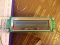
All I get is squares on the first line.

It was working the other day, but I had to mess around with the code, and now it's not working.

I think it is a timer / oscillator problem, but I can't seem to find it.

Can you?
 

Attachments

Last edited:

spinnaker

Joined Oct 29, 2009
7,830
Squares usually mean your contrast is not set correctly. Check with a volt meter.

Also verify each of the connections to the LCD just to be sure you did not mess up a connection between a couple days ago and now. A good way to do this is to write a quick program to toggle each bit and test with a logic probe, scope, logic analyzer etc.

If you use MPLabX, it automatically keeps code changes. I really nice feature.
 

absf

Joined Dec 29, 2010
1,968
4.2.2 WEAK PULL-UPS
Each of the PORTA pins, except RA3, has an
individually configurable internal weak pull-up. Control
bits WPUAx enable or disable each pull-up. Refer to
Register 4-4. Each weak pull-up is automatically turned
off when the port pin is configured as an output. The
pull-ups are disabled on a Power-on Reset by the
RAPU bit of the OPTION register. A weak pull-up is
automatically enabled for RA3 when configured as
MCLR and disabled when RA3 is an I/O. There is no
software control of the MCLR pull-up.
I normally dont use Port A for LCD connection. Try add pull-up resistors on RS & E and see if it works. Else shift them to PORT B if it is available.

Allen
 

Thread Starter

nerdegutta

Joined Dec 15, 2009
2,689
No, I don't.

It get ~5v from a 7805 regulator, with caps on in and out pins.

I think it has to do with initialization and the oscillator.
 

spinnaker

Joined Oct 29, 2009
7,830
No, I don't.

It get ~5v from a 7805 regulator, with caps on in and out pins.

I think it has to do with initialization and the oscillator.
You should have .1uf caps on all of your power pins of all of your chips including the LCD. Not saying that is the problem here but it certainly would not hurt to try since you should add them anyway.
 

t06afre

Joined May 11, 2009
5,934
You have defined _XTAL_FREQ to 4Mhz in the lcd.c and 8 MHz in your main.c Your MCU is running on 8MHz. So this may have messed up your delay timing.
Edit now I see your error. The example you are using are OK then you use two ports. But you use only one port. And at the same time you also have in your code
LCD_DATA = ( ( c >> 4 ) & 0x0F );
So the high nibble of LCD_DATA will always be cleared then writing to PORTA. Hence you will always tell the LCD to expect a command and not data. You must rewrite your code so EN and RS have the correct value before you write to PORTA. EN should be high before the STROBE command and RS according to data command setting. Just use temp variable to work on before you send your data to the port
 
Last edited:

Thread Starter

nerdegutta

Joined Dec 15, 2009
2,689
You have defined _XTAL_FREQ to 4Mhz in the lcd.c and 8 MHz in your main.c Your MCU is running on 8MHz. So this may have messed up your delay timing.
Rich (BB code):
#ifndef _XTAL_FREQ
 // Unless specified elsewhere, 4MHz system frequency is assumed
 #define _XTAL_FREQ 8000000
#endif
What does this mean?

Edit now I see your error. The example you are using are OK then you use two ports. But you use only one port. And at the same time you also have in your code
So the high nibble of LCD_DATA will always be cleared then writing to PORTA. Hence you will always tell the LCD to expect a command and not data. You must rewrite your code so EN and RS have the correct value before you write to PORTA. EN should be high before the STROBE command and RS according to data command setting. Just use temp variable to work on before you send your data to the port
Hm... Need some more guidance here, 'cause this was working....

One more thing is not RA3 input only:eek:
Yup, it is, but I'm not using it.
 

t06afre

Joined May 11, 2009
5,934
Forget my last postings. I read your code wrong. Thinking you used only PORTA as your LCD control port:confused:
Looking again at your code it looks correct. Then using the lower nibble of PORTC. The squares are often a sign of something wrong then setting up. Could it be loose wire some place (no pun), or a bad solder
 

Thread Starter

nerdegutta

Joined Dec 15, 2009
2,689
Forget my last postings. I read your code wrong. Thinking you used only PORTA as your LCD control port:confused:
Looking again at your code it looks correct. Then using the lower nibble of PORTC. The squares are often a sign of something wrong then setting up. Could it be loose wire some place (no pun), or a bad solder
Tried wit 4 different PICs
Tried with 2 different LCD
Tried changing RS and E to ports C, and added R/W
No luck!

All is set up on breadboard, and I've checked for connection between PIC wires and actual contacts on the LCD.

I just don't get it. :(
 

thatoneguy

Joined Feb 19, 2009
6,359
Try toggling an unused port every time through main(), then check the speed with the scope to see if it is a 1 MHz square wave for 8Mhz in (toggle every 4 clock cycles, 1 cycle high, 1 cycle low = 1Mhz out pin)

Are you getting data out on the other LCD lines when you look with a scope?

In lcd.c, the ports are hard coded?
Rich (BB code):
#define LCD_EN RA5  
#define LCD_DATA    PORTC
Since nothing is on portC....
 

Thread Starter

nerdegutta

Joined Dec 15, 2009
2,689
Try toggling an unused port every time through main(), then check the speed with the scope to see if it is a 1 MHz square wave for 8Mhz in (toggle every 4 clock cycles, 1 cycle high, 1 cycle low = 1Mhz out pin)

Are you getting data out on the other LCD lines when you look with a scope?

In lcd.c, the ports are hard coded?
Rich (BB code):
#define LCD_EN RA5  
#define LCD_DATA    PORTC
Since nothing is on portC....
Yes, I get a reading on the scope, when probing the other datalines.

The LCDs shows the same squares.

The LCD data bits are on RC0-RC3
 

thatoneguy

Joined Feb 19, 2009
6,359
Your Original Post shows data on RA0-RA3 in text ? (RA0-3 = D4-7)

If that's not the issue, check the clock.

Maybe try a "known good" lcd app on the PIC with a demo board to compare signals?
 

Thread Starter

nerdegutta

Joined Dec 15, 2009
2,689
Your Original Post shows data on RA0-RA3 in text ? (RA0-3 = D4-7)

If that's not the issue, check the clock.

Maybe try a "known good" lcd app on the PIC with a demo board to compare signals?
My fault. It should be RC0-3 = D4-7. I have corrected the OP. I think it has something to to with clock, initialization or oscillation, but I cannot get my head around it...
 

MrChips

Joined Oct 2, 2009
35,127
Just shooting in the dark.
Try rewriting the LCD_STROBE( ) macro as a separate subroutine
and put some delay between going high and low.

Call lcd_init( ) twice in main( ).

Check timings on the scope and make sure you are not running too fast.
Increase the delays where necessary.
 

Thread Starter

nerdegutta

Joined Dec 15, 2009
2,689
Just shooting in the dark.
Try rewriting the LCD_STROBE( ) macro as a separate subroutine
and put some delay between going high and low.

Call lcd_init( ) twice in main( ).

Check timings on the scope and make sure you are not running too fast.
Increase the delays where necessary.
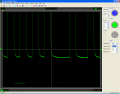
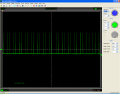
Maybe going too fast. The attachment is from the E bit.

Which reminds me... I had a problem with some ADC acquisition. The error message/warning said something about less that 1.60uS. How can I slow down?
 

Attachments

Top