PIC16F1459 & LCD PC1602LRS config

Thread Starter

Jswale

Joined Jun 30, 2015
121
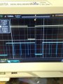
I re-wired and the scope shots now show square waves as expected from looking at the simulation, I have attached them

Image DB7_DB6----------> Blue is DB7, Yellow is DB6
Image DB5_DB4----------> Blue is DB5, Yellow is DB4
Image EN_RS--------------> Blue is Enable, Yellow is RS

It is strange how enable is always high though.

The pot is wired correctly;
Pin 1 is VDD
Pin 2 is Vo
Pin 3 is VSS (on the pot)
 

Attachments

Thread Starter

Jswale

Joined Jun 30, 2015
121
Code:
// PIC16F1459 Configuration Bit Settings

// 'C' source line config statements
#define _XTAL_FREQ 31250
#include <xc.h>


// #pragma config statements should precede project file includes.
// Use project enums instead of #define for ON and OFF.

// CONFIG1
#pragma config FOSC = INTOSC    // Oscillator Selection Bits (INTOSC oscillator: I/O function on CLKIN pin)
#pragma config WDTE = OFF       // Watchdog Timer Enable (WDT disabled)
#pragma config PWRTE = OFF      // Power-up Timer Enable (PWRT disabled)
#pragma config MCLRE = ON       // MCLR Pin Function Select (MCLR/VPP pin function is MCLR)
#pragma config CP = OFF         // Flash Program Memory Code Protection (Program memory code protection is disabled)
#pragma config BOREN = OFF      // Brown-out Reset Enable (Brown-out Reset disabled)
#pragma config CLKOUTEN = OFF   // Clock Out Enable (CLKOUT function is disabled. I/O or oscillator function on the CLKOUT pin)
#pragma config IESO = ON        // Internal/External Switchover Mode (Internal/External Switchover Mode is enabled)
#pragma config FCMEN = ON       // Fail-Safe Clock Monitor Enable (Fail-Safe Clock Monitor is enabled)
// CONFIG2
#pragma config WRT = OFF        // Flash Memory Self-Write Protection (Write protection off)
#pragma config CPUDIV = CLKDIV6 // CPU System Clock Selection Bit (CPU system clock divided by 6)
#pragma config USBLSCLK = 48MHz // USB Low SPeed Clock Selection bit (System clock expects 48 MHz, FS/LS USB CLKENs divide-by is set to 8.)
#pragma config PLLMULT = 3x     // PLL Multipler Selection Bit (3x Output Frequency Selected) 
#pragma config PLLEN = ENABLED  // PLL Enable Bit (3x or 4x PLL Enabled)
#pragma config STVREN = ON      // Stack Overflow/Underflow Reset Enable (Stack Overflow or Underflow will cause a Reset)
#pragma config BORV = LO        // Brown-out Reset Voltage Selection (Brown-out Reset Voltage (Vbor), low trip point selected.)
#pragma config LPBOR = OFF      // Low-Power Brown Out Reset (Low-Power BOR is disabled)
#pragma config LVP = OFF       // Low-Voltage Programming Enable (High-voltage on MCLR/VPP must be used for programming)


#define lcd_port  LATC        // write to LAT, read from PORT
// DB7-DB4 are RC3-RC0 respectively

#define LCD_RSout LATC4  // LCD RS: 0 = command, 1=data
#define LCD_ENout LATC5 // LCD E(nable), active high
// LCD R/W is tied to 'WRITE'

//--------------------- STROBE LCD ---------------------------
// Pulses E line on LCD to write
int strobeLCD(void)
{
LCD_ENout = 1;
__delay_us(1);
LCD_ENout = 0;
}

//--------------------- WRITE 8 BIT DATA TO LCD  -----------------
// Assumes LCD is ready and RS is set to correct value

void writeLCD(unsigned char dat)
{
    lcd_port = ((dat >>4) & 0x0F);  // write upper nibble
    strobeLCD();
`
    lcd_port = (dat & 0x0F);        // write lower nibble
    strobeLCD();

    __delay_us(200);                // wait for display to process
}

//-------------------- WRITE LCD COMMAND  --------------------
// Assumes E is low and display is NOT busy
void lcd_cmd (unsigned char cmd)
{
    LCD_RSout = 0;       // select command register
    writeLCD(cmd);
}

//---------------------- WRITE LCD DATA  --------------------------
void lcd_data (unsigned char dat)
{
   LCD_RSout = 1;       // select data register
   writeLCD(dat);
}
//-------------------- RESET/CONFIGURE LCD  -------------------------
// Delays are generous, trim when able
void lcd_reset()
{
    lcd_port = 0x03;        // direct data to LCD DB7-4
    LCD_RSout = 0;

    strobeLCD();        // write 3h, wait 10ms
    __delay_ms(10);

    strobeLCD();        // write 3h, wait..
    __delay_ms(10);

     strobeLCD();       // write 3h
    __delay_ms(10);
}

//------------------------ INIT AND CONFIGURE LCD  ---------------------
void lcd_init ()
{
    lcd_reset();         // LCD reset
    lcd_cmd(0x28);       // Funciton Set: 4-bit mode - 2 line - 5x7 font.
    lcd_cmd(0x0C);       // Display no cursor - no blink.
    lcd_cmd(0x06);       // Automatic Increment - No Display shift.
    lcd_cmd(0x80);       // Address DDRAM with 0 offset 80h.
}

//======================= MAIN =====================================
void main ()
{
    TRISC=0b00000000;
    PORTC=0b00000000;
    ANSELC=0b00000000;
    TRISB=0b00000000;
    PORTB=0b00000000;
    ANSELB=0b00000000;
    TRISA=0b00000000;
    PORTA=0b00000000;
    ANSELA=0b00000000;


    __delay_ms(300);         // power up delay for LCD

    lcd_init();

    while(1)
{
    lcd_data('H');
    __delay_ms(100);
    lcd_data('E');
    __delay_ms(100);
    lcd_data('L');
    __delay_ms(100);
    lcd_data('L');
    __delay_ms(100);
    lcd_data('O');
    __delay_ms(100);
}
   // while(1);       // wait forever
}
 

JohnInTX

Joined Jun 26, 2012
4,787
// while(1); // wait forever
You can't comment this out. When you do, it re-inits the display microseconds after you load it.
Do you have a PICkit to debug?
Your pictorial says PICAXE on the chip. Presumably you are not using PICAXE?
 

Thread Starter

Jswale

Joined Jun 30, 2015
121
I have added a while loop higher up on line 123 so that H E L L O is re-displayed constantly.

I am using a PIC16F1459, that 'PICAXE chip' is all the libraries had but I have edited it.

So far, everything BUT Enable is a square wave (Enable is constantly HIGH) WITHOUT the LCD plugged in. Once I plug it in then the voltages become steady non oscillating.

Thanks for the help so far!

EDIT: I will have a PicKit debugging facilities tomorrow if the problem is not solved
 

JohnInTX

Joined Jun 26, 2012
4,787
I have added a while loop higher up on line 123 so that H E L L O is re-displayed constantly.
Ahh.. but you are not resetting the data address to the beginning of the line.. I'd just set it up to do it once. At this point, it would be sufficient just to get a cursor. That would indicate that you can write commands to the display.
 

Thread Starter

Jswale

Joined Jun 30, 2015
121
I know, I wanted to make sure that if the data address was not correctly configured, then HELLO would always be spammed on the LCD for testing.

Yeah anything at all would be lovely! haha
 

Thread Starter

Jswale

Joined Jun 30, 2015
121
Just noticed on the ST7066U-OA datasheet for the LCD driver, Fosc needs to be between 190KHz and 350KHz. Will that have cause any problems we are experiencing?
 

JohnInTX

Joined Jun 26, 2012
4,787
OK - how are you programming this thing? Do you have a hardware debugger that you can set a breakpoint with?

So first, I'd mod the code to just init the display.. nothing else. Cursor=success. To get there, you have to see E go pulse low-high-low. Until then, nothing happens. Sometimes its helpful to cut down your code and put in test code. For E, if you don't have anything else, I'd init the IO (not the LCD) then just do this

C:
 while(1){
strobeLCD();
__delay_ms(1); // or whatever works for your scope You should see a valid E strobe every 1ms
}
You can temporarily remove other code using
C:
#if 0
 Lots of code that just became comments
#endif
You can reinstall it by changing the #if 0 to #if 1
The idea is to get bits and pieces working by themselves rather than throwing lots of signals out that are hard to scope.

Even though the power on defaults should be OK, I would explicitly disable the comparators and DAC and ECCP and anything that shares the port pins.
 

Thread Starter

Jswale

Joined Jun 30, 2015
121
I am using a PICKIT3 and MPLAB 8.92 so breakpoints etc are all easily done. Ill try that.

Also in regards to Vo, isn't it operating Voltage, therefore the peak to peak voltage of the square waves will change as the pot is turned?

Ill try all these things @JohnInTX and get back to you tomorrow. Thanks for the help so far.
 
Last edited:

Thread Starter

Jswale

Joined Jun 30, 2015
121
@nerdegutta you don't understand. This has nothing to do with PICAXE. That is just the default chip on the design software I am using in the wiring setup, it is only for aesthetic purposes. I am using a PIC16F1459 with MPLAB v8.92 and a PICKIT3
 

nerdegutta

Joined Dec 15, 2009
2,684
@nerdegutta you don't understand. This has nothing to do with PICAXE. That is just the default chip on the design software I am using in the wiring setup, it is only for aesthetic purposes. I am using a PIC16F1459 with MPLAB v8.92 and a PICKIT3
OK, but how have you connected the PICKit3? I cannot see any connections on pin 1, 4, 15, 16, and 20. You should also have a resistor from pin 4 to VDD. I'm referring to the picture in post #22.
 

JohnInTX

Joined Jun 26, 2012
4,787
OK, but how have you connected the PICKit3? I cannot see any connections on pin 1, 4, 15, 16, and 20. You should also have a resistor from pin 4 to VDD. I'm referring to the picture in post #22.
The power is connected (hard to see) and you don't need anything connected to the ICSP lines if you haven't built for debug BUT.. pin 4 should indeed be pulled up since MCLRE = ON in the config bits.

Good catch.
 

Thread Starter

Jswale

Joined Jun 30, 2015
121
I transfer the PIC to a programming breadboard to do the programming @nerdegutta, I will install the pull up resistor.
Maybe that is causing the problems and is pulling MCLRE low....
 
Top