 Facebook
 Google
 GitHub
 Linkedin
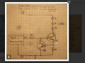
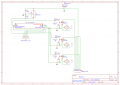
I've completed a perf board circuit that uses multiple (three) N channel MOSFETS to control the lighting of three blinking LEDs (high power). The blinking is controlled by a PIC10F200, which has 3 GPIO pins that are used to trigger the separate circuits. I had previously programmed this mcu in machine language and tested it on a breadboard. The mcu and programming is/was working just as intended, as demonstrated by the low power application on the breadboard. The schematic for the "high power" LED circuit comes from Instructables. That schematic and and my 3-up version are attached. Please note that the flashing pattern is such that no 2 LEDs are on or supposed to be on at the same time - the 3 output pins on the PIC have an exclusive time allocation for when they are set high (LED is on) and each pin is set low (BCF) before the next pin is set high (BSF), and so on.
Problem: the PIC programming appears to be working but during each pin's off period, that LED is showing a dimmer, but very recognizable, illumination that mimics the blinking pattern of the pin circuit that is set high at the time. One can follow the rotation of the flashing pattern and determine that the programming is working fine by noting the brightest light that is on. But, as said, the other lights are also illuminated but are somewhat dimmer than the circuit that is currently set to high. The problem is worse at startup and improves with time - changes are very noticeable in 3 minutes or so.
Input V is 13.5V (automotive) and there is a 7805 that provides power to the mcu. For the pullups, I've tried 100kR in place of the 10KR to no effect. Also added 100KR for pulldowns to no effect.
If the bleed over lighting was more random or clearly disconnected from the PIC, I'd be more suspicious of the MOSFETS, et al but since the unwanted illumination is same blinking pattern as the pin currently set to high, seems like it has to be a PIC problem. Internal damage?
Thanks to all in advance.
Larry
Attachments
-
 250.5 KB Views: 11
 -
 75.3 KB Views: 10


