PIC Microcontroller Question

Thread Starter

bwilliams60

Joined Nov 18, 2012
1,442
I am working on an automotive scan tool that will not power up. There is no schematic so I am working blind. I have found the LTC4412 PowerPath controller and have voltage from the battery (pin 1- 9.27VDC) and the AC adapter(pin 6-14.90VDC). I am not sure which pin is the output pin but I have 0V on pins 2 and 4, 7V on pin 3 and 14.79V on pin 5. My first question would be what voltage should I expect and what pin should be the output?
https://www.analog.com/media/en/technical-documentation/data-sheets/4412fb.pdf
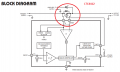
My second question has to do with the voltage regulator MP2467DN. I have 14.9 VDC at pin 7 (Vin) and my ground at pin 5 is good. I have no output at pin 1. Is there anything else needed by the regulator to turn on and output a voltage? I am thinking it should be 3.3VDC. I have a 10uH inductor right beside it.
I have no Vdd at my microcontroller.
https://www.mouser.ca/datasheet/2/277/MP2467-1368026.pdf
If I disconnect the AC adapter, I do not see battery voltage at pin 7 of the regulator.
This scan tool should power up through the OBDII connector, the AC adapter or the battery. The adapter takes precedence over the battery.
Any suggestions?
 

Thread Starter

bwilliams60

Joined Nov 18, 2012
1,442
Well it looks like I might have to go solo on this one. So I looked at the datasheet for the regulator and if I read it correctly, pin 2 has to have some voltage on it in order for it to fire up the regulator. Maybe someone can correct me if I'm wrong. So i traced it back and came across 10 legged IC with the number 0G528 followed by 2102D. The connection is to pin 10. Any ideas on what this might be? I think this has to provide a square wave signal to pin 2 of the regulator
 

Attachments

Last edited:

Thread Starter

bwilliams60

Joined Nov 18, 2012
1,442
That is what I figured. Now I just need to figure out how I get that higher voltage but I a, stuck at this 10 legged device. Not sure what it ismor what makes it go? May be a t a crossroads me thinks.
Happy New Year.
 

Thread Starter

bwilliams60

Joined Nov 18, 2012
1,442
Question about LTC4412. In the attached diagram, there is a diode across the source and the drain at pins 1 and 6. See diagram.
My question is this. Should I be able to test this diode with my DVOM as any other diode? It looks to be an external MOSFET and I know when I check my voltage regulator, there is no voltage present if I disconnect my wall adaptor so I am assuming that this diode is open. Thoughts.
https://www.analog.com/media/en/technical-documentation/data-sheets/4412fb.pdf
 

Attachments

Papabravo

Joined Feb 24, 2006
21,225
You cannot test the diode by itself because it is in parallel with the P-channel. The tester will apply a voltage difference to the drain and the source and you will be trying to test two things in parallel with no voltage on the gate. With the gate floating it might do anything further confusing any attached instrument. The diode is often drawn as a zener which means it has a reverse breakdown voltage as well as a forward voltage. I would not place any confidence in any readings you might obtain.
 

Thread Starter

bwilliams60

Joined Nov 18, 2012
1,442
I'm back to this unit and now I have a question about the microcontroller. The datasheet for MP2467 above says that Pin 2 must be enabled to output a voltage. I have system voltage at the ready on pin 7 at 13.6V so this chip is not turning on. When i follow pin 2, it leads to a PIC16F886 microcontroller. So now I am stumped. How do I figure out what is required for this microcontroller to put voltage to that pin? I have 3.3V into the micro and ground is good. That much I can figure out. Is there a developer tool or something that I can connect to it to see if it is functioning properly?
http://ww1.microchip.com/downloads/en/devicedoc/41291d.pdf

@Papabravo or @MaxHeadRoom , perhaps you might have some insight on this?
 
Last edited:
Top