 Facebook
 Google
 GitHub
 Linkedin
Hi,
Designing a power control board, controlling various loads. Trying to make it universal as possible, targeted 16A max load only for switching and 5A for dimming with a triac.
Using XC8 v1.38, cpu as 18F25k22, using internal crystal and PLL with 64Mhz clock.
Also this board will make some measurements and energy calculations for various purposes.
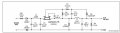
General layout is as it is:
The power supply part is as:
There is 7805 regulator and 100nF + 100uF decoupling capacitors after the 12V output, to get 5V DC.
By code , using phase control driving the triac and controlling the load power. As expected with resistive loads it is all ok.
The delay, for testing is constant, changing every time, no dynamic part.
From B0-pin getting a INT0 and setting a delay according to the power level. Also for testing set a pin toggle and from the oscilloscope I see a square-wave with 20ms period, as expected for the 50Hz line.
When using inductive loads like a motor strange thing happens:
When there is no load or there is a resistive load the zero-cross interrupt pin signal is 10ms / 10ms as expected but when the there is the motor , it becomes something like 6ms / 14ms ! So the triac drive starts to make errors because hte zero cross is not ok.
At the time of the motor run, checked the B0 pin signal, it is ok 10ms/10ms square wave. So some noise should be affecting inside the PIC , the interrupt.
I know this should be definitely related to Analog-Digital ground thing, so tried to separate analog and digital ground ( from the power supply , 1N4007 actually connects them), or taking out the diode 1N4007 from the supply and putting a ferrite between grounds. No luck.
Measured the power supply of 5V, with oscilloscope, seems ok , low ripple like 50mV.
Then tired to measure the 5V-ground with the EARTH ( after isolating the oscilloscope ) , and the is a huge spike starting with 250V and getting smaller for 25usecs ! So I thing the motor load is affecting the ground reference of the PIC and since the zero-cross part is dependent of the diodes of the B0 port, and the reference ground is affected, the timing of zero-cross is changes.
Tried to put a transformer based power supply also, the problem only seem to happen for the starting 500msecs or so, after the motor is running the zero-cross signal is ok, but the problem is dont want to use transformer supply because of the space.
Stuck for days.
Any ideas ? Any opinion to test ?
Designing a power control board, controlling various loads. Trying to make it universal as possible, targeted 16A max load only for switching and 5A for dimming with a triac.
Using XC8 v1.38, cpu as 18F25k22, using internal crystal and PLL with 64Mhz clock.
Also this board will make some measurements and energy calculations for various purposes.
General layout is as it is:
The power supply part is as:
There is 7805 regulator and 100nF + 100uF decoupling capacitors after the 12V output, to get 5V DC.
By code , using phase control driving the triac and controlling the load power. As expected with resistive loads it is all ok.
The delay, for testing is constant, changing every time, no dynamic part.
From B0-pin getting a INT0 and setting a delay according to the power level. Also for testing set a pin toggle and from the oscilloscope I see a square-wave with 20ms period, as expected for the 50Hz line.
When using inductive loads like a motor strange thing happens:
When there is no load or there is a resistive load the zero-cross interrupt pin signal is 10ms / 10ms as expected but when the there is the motor , it becomes something like 6ms / 14ms ! So the triac drive starts to make errors because hte zero cross is not ok.
At the time of the motor run, checked the B0 pin signal, it is ok 10ms/10ms square wave. So some noise should be affecting inside the PIC , the interrupt.
I know this should be definitely related to Analog-Digital ground thing, so tried to separate analog and digital ground ( from the power supply , 1N4007 actually connects them), or taking out the diode 1N4007 from the supply and putting a ferrite between grounds. No luck.
Measured the power supply of 5V, with oscilloscope, seems ok , low ripple like 50mV.
Then tired to measure the 5V-ground with the EARTH ( after isolating the oscilloscope ) , and the is a huge spike starting with 250V and getting smaller for 25usecs ! So I thing the motor load is affecting the ground reference of the PIC and since the zero-cross part is dependent of the diodes of the B0 port, and the reference ground is affected, the timing of zero-cross is changes.
Tried to put a transformer based power supply also, the problem only seem to happen for the starting 500msecs or so, after the motor is running the zero-cross signal is ok, but the problem is dont want to use transformer supply because of the space.
Stuck for days.
Any ideas ? Any opinion to test ?
Attachments
-
 142.8 KB Views: 17
 -
 32.4 KB Views: 14
Last edited by a moderator:


