PIC 16f877A - "Target Device ID (0x0) does not match expected Device ID (0xe20)."

Thread Starter

EclecticElectric

Joined Aug 3, 2011
8
Good Evening Everyone!,

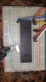
I am an electrical engineering student and recently chose to start working with microcontrollers to gain more practical experience with my major. I began working on the "hello world" blinking LED project about a week ago and have hit a few snags; a couple of them I have solved on my own with some research online but the latest one I can't seem to figure out.

I am using MPLabX with the XC8 compiler, PICKit 3, and the PIC16f877A.

My code builds successfully but with everything connected and powered up I get this from the MPLab X Output Window:

"Connecting to MPLAB PICkit 3...
Firmware Suite Version.....01.32.10
Firmware type..............Midrange

Target detected
Target Device ID (0x0) does not match expected Device ID (0xe20).

The following memory area(s) will be programmed:
program memory: start address = 0x0, end address = 0x7ff

Programming...
program memory
Address: 0 Expected Value: 120a Received Value: 0
Failed to program device"


I found a thread about this on the Microchip forums here( http://www.microchip.com/forums/m672761.aspx) but none of the solutions have worked for me. Any help is greatly appreciated!
 

tshuck

Joined Oct 18, 2012
3,534
Have you measured the supply voltage?

Do you have anything connected to the ICSP pins, aside from the PIC?

How is your crystal/resonator/oscillator connected? (This PIC doesn't have an internal oscillator)

Perhaps you should post a picture of your setup...
 

BMorse

Joined Sep 26, 2009
2,675
I would second ErnieM on this one too.
I would check to make sure all connections are where they are supposed to be, then also make sure the pic is powered, either through the pickit or by another external means.
 

Thread Starter

EclecticElectric

Joined Aug 3, 2011
8
I am using a 3.3v power supply which is connected to Vdd and the ground is on Vss (pins 11 and 12 on one side and 31 and 32 on the other). I have confirmed 3.3v throughout the breadboard, is there another way to ensure the microcontroller is actually powering up?

I am using a 4MHZ crystal oscillator which is connected to OSC1 (pin 13) and OSC2 (pin 14). As far as having something connected to the ICSP pins...I am not sure what you are referring to. I reviewed the data sheet and don't see anything referred to as "ICSP."

Here is the schematic of how I have it set up (I thought it'd be easier to decipher than a photo). The only additional component I have, which is not listed on the schematic, is the 10k ohm resistor that gos from PGM to ground which was a suggested fix for the issue I am experiencing.
 

tshuck

Joined Oct 18, 2012
3,534
The pull down is only necessary when using low voltage programming...


In-Circuit Serial Programming (ICSP - datasheet, page 160) is what the Pickit is connecting to - PGC, PGD, etc. If these pins are loaded, like they are in the schematic you found, the Pickit may not be able to communicate properly with the PIC. Try removing the other connections from PGD and PGC and only connect those pins to the Pickit to see if that allows the pic to be programmed.

If doing this doesn't help, check your configuration bits (read the datasheet for more information).
 

ErnieM

Joined Apr 24, 2011
8,377
That schematic indicates trouble. As tshuck said the PGC and PGD pins need to be driven by the PICkit. So does the MCLR pin (for the Vpp function) so best add a 10K pullup to Vdd there.

Low voltage programming (LVP) is a possibility using the 3.3V but there are severe limitations such as no bulk erasing (something I do all the time when programming). I've not done any LVP so can't advise any further.

Can you add your PICkit connections to the schematic? Or are you programming out of circuit?
 

Thread Starter

EclecticElectric

Joined Aug 3, 2011
8
Thank you very much for the insight everybody, I really appreciate it.
I am using the PICKit 3 to program the microcontroller in circuit.

I believe you guys are right, I triple checked to ensure the PICKit 3 was connected to the terminals of the microcontroller properly. I did not think of the resistor/diode causing issues with the communication but that certainly seems feasible. I got a pretty busy week but I will check over things this weekend and let you guys know.

Again I really appreciate all the support, the insight has been fantastic!
 

Thread Starter

EclecticElectric

Joined Aug 3, 2011
8
Sorry for the delay everyone.. I got a couple new power supplies and stripped the breadboard of everything but the power supply, microcontroller, PICkit 3 connections, oscillator, and the two capacitors shown in the schematic above.

I am no longer getting the original error which was amazing to see (thanks!). However I am now getting:
"Address: 0 Expected Value: 120a Received Value: 0
Failed to program device"

For what it is worth it says "Programming" for 10-12 seconds before showing the error - having never seen it work correctly, I assume this implies good communication between the PICKit and the 16f877a.

With regard to what Ernie mentioned about LVP programming, could this be causing the issues even though the data sheet says the operating voltage is 2-5v? Or is this perhaps a configuration problem with my MPLab X?

I really appreciate everyone's help!
 

ErnieM

Joined Apr 24, 2011
8,377
However I am now getting:
"Address: 0 Expected Value: 120a Received Value: 0
Failed to program device"
That is actually good news, you have definitely made some progress. To get that place you needed to pass the ID test where Target Device ID (0x0) does indeed match expected Device ID.

So all the connections seem to be correct. Data and clock for sure. That leaves the voltages; as far as I know a PIC cannot be programmed with less that 2V on Vdd: it seems to work but the readback never passes. MCLR once needed to be about 13V or so because it was used to inject charge into PROM memory, but type is not used anymore so all MCLR does is trip a analog switch by it's level.

Do you have a scope to peek at the program process? It is probably too fast to see anything o a DMM.

Aside: It is exactly problems of this nature I so strongly recommend starting off with a fully assembled and tested programmed (PICkit 2 or 3 is great) *and* a fully assembled and tested development board. Otherwise there can be an overwhelming number of hurdles for the beginner to jump.
 

takao21203

Joined Apr 28, 2012
3,702
11.5v are normaly enough.

but the wires for ICSP should not be too long, the power supply must be suitable, and the minimum loading resistor on DAT/CLK is 2.2K or they dont work.

As well connect nothing to MCLR except a resistor (but the programmer can/does drive it actually).

An oscillator isnt neccessary for flashing.

Shorts on any pins can also cause errors.

You should by all means have spare ICs available.

Yes it can take a lot of efforts to get along with blank chips, and even after years it can fool you again.

Many modern PICs also have voltage regulators and A/D supplies that need to be dealt with.

It is important you figure out what you did wrong, so you can take care of it in the future.
 

Thread Starter

EclecticElectric

Joined Aug 3, 2011
8
ErnieM,

It is interesting you bring up using fulled assembled/programmed development boards..When I first wanted to get into microcontrollers I literally spent about 3 weeks just trying to figure out what I needed. I had no one to ask (I am in the Coast Guard and take classes online) and frankly I would expect some pretty good flaming asking such a broad question on a forum such as this. The most difficult part is not knowing what anything is called; in retrospect I could now have searched "development board" and probably would have ended up in the right direction. I have found a few great videos listed throughout these forums but the microcontroller community is not very easy to break into with little knowledge of required components, parts, etc. Do not get me wrong, I love working with and troubleshooting electronics so I enjoy trying to figure these things out. The steep learning curve associated with this type of project will surely make the end result all the more satisfying. The most exciting part is I know once I successfully get through this demo project I can move on to something a bit more creative. That being said I must continue to express my gratitude toward each of you who are helping me out!

One thing I am unsure of is what is considered "Low Voltage Programming"? I'm getting 3.3v to VDD and using this breadboard power supply. However, I cannot find proper documentation about how to change the output to 5V and last time I tried figuring it out was when I fried the other power supply and had to order a new one.

Also, on the output from MPLab X: "Address: 0 Expected Value: 120a Received Value: 0" what exactly is this referring to? My first thought that it had something to do with the configuration BITs as mentioned above but the "120a" really throws me off. The data sheet mentions that configuration bits which left at 0 can be programmed and those left unprogrammed read as 1.

Since my previous post I have removed the breadboard power supply (using USB power through the PICKit 3), swapped in a fresh PIC16f877A, and removed all VDD and VSS connections to breadboard ground/power (all VDD and VSS going through PICKit 3). The error is unchanged.

I've attached a picture of the configuration (there isn't much to it) as requested. Ignore the resistor thats placed in row 30 of the breadboard; I just put it there so I remembered what it was.
 

Attachments

JohnInTX

Joined Jun 26, 2012
4,787
You have several problems with the picture:

Pins 11 and 12 also need to be connected to Vdd/Vss. You should decouple each pair of power pins with a 1uF tantalum in parallel with a .1 ceramic.
Add a 10K-33K pullup on pin 1 MCLR/ so that when PICkit releases it to run, it will.
The caps on the oscillator are WAY too big. Use 22-33pf and connect the common ground back close to pin 12 (Vss on the PIC). Easier is to buy a canned DIP oscillator like the ACH(L) stuff here. You can see if your oscillator is running by measuring the voltage on OSC2, it should be 1/3 to 1/2 of Vdd. If the osc is not running, it will be Vdd or Gnd. Your oscillator is not running with those caps.
Presumably the crystal is the correct type and you have configured the PIC for XT or HS oscillators, yes? HS will work OK for most - it can overdrive some low freq xtals but meh for now..
You probably don't need the connection to pin 36 (LVP).
For now, power the PIC from the PIKkit. Are you using 5V?

Pull up RC0 with a 1K resistor then-
Write a stupid program that just:
sets TRISC to 00h
sets PORTC to 00h
do a do-nothing loop ( while (1) or goto $-1 )
Since the PIC IO comes up as inputs if the PIC is dead, the voltage on RC0 will be high. If it goes low, the PIC is running (assuming you have it powered.. If it stays high, the PIC is not running). Continue.

Also, on the output from MPLab X: "Address: 0 Expected Value: 120a Received Value: 0" what exactly is this referring to? My first thought that it had something to do with the configuration BITs as mentioned above but the "120a" really throws me off.
This means that the processor is not running, probably due to the problems above. Its trying to program the first instruction but it fails, reading 0000 usually means an inert PIC rather than a real programming error. Config bits don't factor into this.. - yet. You can program any configs you like and get a good verify - the PIC won't run if the config is bogus but you'll at least get a good verify...

A good starting place is to look at the Microchip development board manuals. Here (click Development Tools) you'll find links to the various boards that support the 877A. The manuals have the schematics of the boards which will shed lots of light on what you have to do to get a good hardware set.

frankly I would expect some pretty good flaming asking such a broad question on a forum such as this.
Not here, you won't. But, I agree with ErnieM, many PIC demo boards are dirt cheap and plug right in. And apologies if I am redundant, I only scanned the previous posts.

Good luck and thanks for your service.
 
Last edited:

ErnieM

Joined Apr 24, 2011
8,377
(This post uses a lot of words to basically say "hrmm, I'm at a loss too.")

Programming is different from the computer portion. It uses task specific hardware where the only clock required is the external clock on the data you give it. So one thing is you do not need the crystal there to program and verify the program.

"Address: 0 Expected Value: 120a Received Value: 0" is pretty simple: Address 0 is the very first instruction run by the processor. The code inside the hex file (made from the program code) has a value of 120 for the instruction that goes here. However, after reading a proper device ID, then programming all the locations, a read back failed, and instead of reading a value of 120 it instead read 0. No data, like either the device did not program or the wrong data was received.

When a PIC is erased all the bit values are set to 1, so somehow you are either loosing the data connection when you are writing data, or when you are reading it. You might see something if you put a voltmeter on the data line during programming, but after device ID reading, so in the middle of the programming time. (I do admit I am somewhat lost as to what is happening here.)

Ahh... one worry is now out of the way. Per the data sheet: "The High-Voltage Programming mode is always available, regardless of the state of the LVP bit, by applying VIHH to the MCLR pin." So you can always bypass a chip that's been set to low voltage mode. I am still wondering why you have a wire on pin 36: where does that go?

(So stop worrying about low voltage programming: you don't use it and it needs not be used.)

Can you pull the camera back a bit and show the breadboard and the PICkit? I'm mostly curious as to what is happening with the PICkit. I've used a PICkit with about 6" of wire between PIC and kit without any problem. I like your test rig here, strip it to the simplest thing that works, then build up from there.

EBay is my personal source of cool things. Many of them come from China with free shipping it takes 2-3 weeks to get to me here in NY. I did a quick search using "PIC16F877A board" and found this board.

Now a personal aside to you: in one post you mentioned not wanting to get flamed for asking some questions. However, when you talk about what you did but did not understand, or are doing but need a push, you are wearing magic anti-flaming armor because you used the magic words: "I did." We love to help people actually doing something. If you came back and said "hey, it was x and now it works." you make our day.

What we hate are people who ask if they can "get the codes" to make their project work, as if there is a magical program out there that does exactly what they need, or can someone write something for them. And we save a special set of taunts for people who expect us to be their special search engine.
 

Thread Starter

EclecticElectric

Joined Aug 3, 2011
8
haha Ernie, I loved that search engine link, never so that one before. I poked around a bit to figure out what I could about development boards such as the one you linked. Are the development boards essentially a stable platform for programming the respective microcontroller? I'm not sure I completely understand what purpose they serve aside from that. However if that is the case I will most likely purchase one to eliminate the current issue I am having (although my pride will not allow me to completely stop trying to correct it!).

I changed the configuration bits for the Oscillator to HS and still received the same error. Further suspecting the oscillator as recommended I completed removed the oscillator from the circuit and got the same error from MPLab. I also read OSC2 to ground and read ground. This seems to confirm that the error lies within the oscillator setup.

Unfortunately at this time, the 1uF capacitors are the smallest size I currently have so I will need to order much smaller ones to test further.

I was reading more through the data sheet and found a Note that mentioned:
"Higher capacitance increases the stability of oscillator but also increases the start-up
time"

Could the issue be that the oscillator is starting up too slowly causing a lack of response from the microcontroller to the PICKit 3 then causing the MPLab operation to time out?

I will be sure to update the post when I get the smaller oscillators in, although it may not be for a week or so.

Thanks
 

ErnieM

Joined Apr 24, 2011
8,377
IT IS ABSOLUTELY NOT THE OSCILLATOR CAUSING THIS PROBLEM. Final Answer.

Wow, I never said anything in all caps before. The oscilator is not running during programming. How can it be running, when one of the functions of programming is to set the type of oscillator being used? Just pull the oscillator stuff and see if you can get it to program.

The PICkit stand-alone app may be easier to use to bang tests into and out of your PIC. I much prefer it to MPLAB unless I'm doing in circuit debugging too.

Thinking your problem over has me worried that the PICkit itself is damaged such that the data line cannot go high when driving your device, or cannot read a high when reading. The only way to tell is to drop a scope or a fast voltmeter during programming. Readback happens way too fast to see with a voltmeter.
 

Thread Starter

EclecticElectric

Joined Aug 3, 2011
8
haha Roger, the oscillator is not the problem :-X...sorry I did not know if perhaps during programming the oscillator was checked to ensure proper configuration...I will move past that.

As far as the PICKit maybe being damaged, that puts me in a tough position. I have no access to an oscilloscope and I can't really return the PICKit either. As far as the development boards...would it be worth purchasing one such as the one you linked to confirm my hardware is good? Then perhaps work backwards into the software?
 

ErnieM

Joined Apr 24, 2011
8,377
I could not answer if you should go buy something. I can recommend things, but the decision is always yours based on your budget vs everything else in your life. I just think it makes things way way easier.

Here's why.
More on why.

With no scope to beg/borrow/steal and no voltmeter (Harbor Freight has a starter model for $2 when it is on sale) maybe a LED will show something. Connect to the data and clock lines with a fairly large resistor: just enough current so you can see they are on so you don't load down the signals very much.
 

paulfjujo

Joined Mar 6, 2014
23
Never put so big capacitor for oscillator
normal value is 22pF up to 33pF
For use with ICSP, you don't need Oscillator (Quartz+condo)

Apply power supply to both pins
11, and 32 Vdd +5V
12, and 31 Vss 0V

Instead of Vdd ICSP , you can use an external power supply 5V

Pin 1, MCL/VPP must be tied to +5V trough a resistor 4.7K up to 10K


18F_ICSP.jpg
 
Top