Facebook
 Google
 GitHub
 Linkedin
Hi All,
I apologize if its a very basic question but this is related to my quest to know the things deeply.
The main question or objective to ask this question is to understand what is actually happening in a circuit with one resistor and how the voltage drop happened across resistor. I just need some help from expert like you to please read this and let me know if this is exactly what is happening in the circuit.
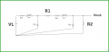
I generated a test circuit as mentioned below :-

In the above test circuit we have two resistors, one is 800 ohm and the other resistor is 1 ohm, basically one ohm resistor is connected to simulate the behaviour of load in the circuit. I have also labelled the circuit diagram with A1, B1, C1, D1 and E1 etc so it will be easy for me to reference the places with charge accumulations in the figure. The main objective of this analysis is to study how the voltage is dropped against a resistor.
As per my analysis when we turned on the battery the charge will start accumulating at point A1 and B1, since A1 is close to the positive terminal of the battery therefore more positive charges will start accumulating at A1 and more negative charges are accumulated at B1, there are some positive charges are also present at B1 but most of the charge accumulation is negative and I am also concerned about accumulated charge impact therefore only negative charges are drawn, similar case happened with R2 where charges are accumulated across resistor terminal in the same way as happened in R1.
The main analysis
Negative charge accumulation at B1 and C1 exerts coulomb force (which is repulsion for negative charges) to negative charges at D1, E1 and F1. Let's call this force F2. Force generated by the battery electric field is F1. This is a non-coulomb force and this non-coulomb force is actually the main driving force of the circuit.
The force experienced by the electron at E1 is equal to F1 - F2 and this will be the cause of potential drop at R2 and this potential drop is experienced by the load which is in this case R1.
I apologize if its a very basic question but this is related to my quest to know the things deeply.
The main question or objective to ask this question is to understand what is actually happening in a circuit with one resistor and how the voltage drop happened across resistor. I just need some help from expert like you to please read this and let me know if this is exactly what is happening in the circuit.
I generated a test circuit as mentioned below :-
In the above test circuit we have two resistors, one is 800 ohm and the other resistor is 1 ohm, basically one ohm resistor is connected to simulate the behaviour of load in the circuit. I have also labelled the circuit diagram with A1, B1, C1, D1 and E1 etc so it will be easy for me to reference the places with charge accumulations in the figure. The main objective of this analysis is to study how the voltage is dropped against a resistor.
As per my analysis when we turned on the battery the charge will start accumulating at point A1 and B1, since A1 is close to the positive terminal of the battery therefore more positive charges will start accumulating at A1 and more negative charges are accumulated at B1, there are some positive charges are also present at B1 but most of the charge accumulation is negative and I am also concerned about accumulated charge impact therefore only negative charges are drawn, similar case happened with R2 where charges are accumulated across resistor terminal in the same way as happened in R1.
The main analysis
Negative charge accumulation at B1 and C1 exerts coulomb force (which is repulsion for negative charges) to negative charges at D1, E1 and F1. Let's call this force F2. Force generated by the battery electric field is F1. This is a non-coulomb force and this non-coulomb force is actually the main driving force of the circuit.
The force experienced by the electron at E1 is equal to F1 - F2 and this will be the cause of potential drop at R2 and this potential drop is experienced by the load which is in this case R1.
")