photoresistor / LDR detect dark help

Thread Starter

Fariida

Joined Jan 22, 2015
13
Hi All,

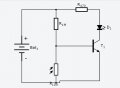
I have made a circuit to detect the dark to turn on an LED but am having trouble understanding on which resistor to use on the LDR. Here is my current set up.


If I use anything less than the 1M resistor the LED just stays on no matter what. Is there something I'm doing wrong?
 

Attachments

MikeML

Joined Oct 2, 2009
5,444
You need to tell us the dark resistance and resistance under full illumination of your specific LDR. There are hundreds of different types.

However, we can divine what your circuit is likely doing. I am guessing on the transistor type and the battery voltage. Here I show how the current through the LED is affected by the resistance of the LDR. I am not very impressed with your circuit; you could do a lot better.

18.gif
 
Last edited:

AnalogKid

Joined Aug 1, 2013
11,056
You have the LDR in the right place, but we need the LDR data mentioned above. We also need to know the LED characteristics (forward voltage, nominal current) and battery voltage. But there are some things we can work out without that information. The description is a bit vague so you can work out the details on your own, but it shows one approach to designing the circuit. Everything here uses only Ohm's Law.

Lets assume a 9V battery, a normal little LED with a forward current of 20 mA, and a typical small signal transistor like a 2N4401 for T1. That transistor has a gain of around 100, so you need at least 200 uA of base current for the LED to start to come on. This gives a maximum value of 420K for the upper resistor. Because the LDR is not a switch, the upper resistor will have to be smaller than this because the LDR will steal some current away from the transistor even when it is at it's max value.

Next, we know that the base voltage will have to be below 0.5V for the transistor to turn off. With 420K and 9V, that gives 24.7K for the maximum LDR "on" resistance to assure that the LED is off.

ak
 

MikeML

Joined Oct 2, 2009
5,444
Here is a better circuit, using the same basic approach and LDR model as above. Note that this one gets about 15mA into the LED and has a much more abrupt turn-on. Next step is to add some hysteresis.

18a.gif
 

Dodgydave

Joined Jun 22, 2012
11,307
As soon as 0.7 v appears across the Ldr, the transistor will switch on, you can use a Darlington pair, or put a couple of diodes in series with the base of the transistor to up the voltage.
 

Thread Starter

Fariida

Joined Jan 22, 2015
13
Thanks all for your replies, I will report back with the necessary results, I wanted to do it last night but it appears my multimeter is broken :-(.

Also I am just a beginner, and doing this as a hobby.
 

MikeML

Joined Oct 2, 2009
5,444
Oh, I forgot to mention, I am using 9V and an NPN transistor with a blue led light
So my guess wasn't too bad... The blue LED has a much higher forward voltage drop than the red one I showed in the sim. That means your circuit will likely get even less current into the LED... Try the Darlington connection with two NPNs...
 

Thread Starter

Fariida

Joined Jan 22, 2015
13
So my guess wasn't too bad... The blue LED has a much higher forward voltage drop than the red one I showed in the sim. That means your circuit will likely get even less current into the LED... Try the Darlington connection with two NPNs...
Ok, I will give that a try, Thanks!
 
Top