PhotoGate control with MCU GPIOs.

Thread Starter

BuckyFuller

Joined May 10, 2018
3
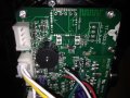
I have an active device that has photogates. As the IR diode emits across a small gap, the detector base is driven. This component is active low. When this gap between IR emitter from IR detector is blocked with a plastic tab, a motor runs. I would like to control the state of each with mcu's GPIO ports. What is the best way to do this?
Ty kindly,
John
 

MrChips

Joined Oct 2, 2009
30,706
Welcome to AAC.

It is not clear what you are asking.
Elaborate on what you mean by "control the state of each".

Each what?
What do you mean by "state"?
What do you mean by "control"?
 

Thread Starter

BuckyFuller

Joined May 10, 2018
3
Thanks for your reply. This project is a mini powered two wheeled Segway knock off. When rider steps on platform, plastic tabs underfoot block photogate to control ride. As tab blocks Detectors from static IR directed across a gap, direction is controlled. My goal is to control the photogate at Detector side. The IR diode drives the base of phototransistor unless blocked by the plastic tab. When this phototransistor turns off, the wheel actives. I would like to control this remotely with app or write a planned route in C. How can I tie MCU into Segay PCB to act as if the plastic tab were turning off detector on command?

http://www.utopiamechanicus.com/article/arduino-photo-interruptor-slotted-optical-switch/

"Each" photogate.
"State" on or off
Use MCU to "control" on vs of state of phototransistor pulling current from collector
 

Attachments

MrChips

Joined Oct 2, 2009
30,706
Let me see if I understand this correctly.

You wish to disable the function of the photogate and use a signal from an MCU GPIO.

Remove the photogate. If the voltage levels of the MCU GPIO are the same as those on the Segway, all you need is a resistor connecting the two. If the voltages are different, you will need voltage level converters.
 

Thread Starter

BuckyFuller

Joined May 10, 2018
3
Let me see if I understand this correctly.

You wish to disable the function of the photogate and use a signal from an MCU GPIO.

Remove the photogate. If the voltage levels of the MCU GPIO are the same as those on the Segway, all you need is a resistor connecting the two. If the voltages are different, you will need voltage level converters.
Yes we are on the same page MrChips. Thanks for your patience. Would it be possible to leave photogate and add a switch to toggle from ride (actual person) mode to read (MCU GPIO ) mode?
I agree, the dc to dc conversion will have to happen. I measured .112 V on detector side when photogate is open from tab(no one riding) and 2.170 V when photogate is block from tab(depressed from riders weight distribution).
Do I convert Vgpio = 5V to Vdector = 2.17V ?
There are 4 photogates so best case I get to leave photogate as to not disable ridable too. Worse case photogates deleted but mcu control gained.
I value your input.
John
 

MrChips

Joined Oct 2, 2009
30,706
You need to figure the logic function desired with two inputs.

Draw a truth-table with four possible input conditions:
Photo-gate unblocked and blocked.
MCU output FALSE/TRUE

Then show the desired outcome.
 
Top