Phillips PM 3322 Osc no beam

Thread Starter

homerwsmith

Joined Jul 7, 2018
20
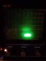
I was working with my Teac the other night and before my eyes the beam on my scope
started to fade, and about 2 hours later it was gone for good.

Focus, alignment and functionality were all good until the end.

What am I dealing with with here, a bad CRT, or a bad voltage to the grid?

Anything else?

I have the service manual, the scope is a very simple split beam transistor 10Mz scope
from way back.

The INTENSITY/FOCUS circuit is relatively simple, the -1500HV is good

Attached is pdf of the pertinent area of the circuit diagram if anyone is interested.

Homer W Smith
CEO Lightlink Internet
 

Attachments

AlbertHall

Joined Jun 4, 2014
12,345
Switch it off.
Short grid and cathode - be certain to get the right pins!
Switch it on.
If a very bright trace appears then the problem is with the brightness control circuits that set the voltage on these two electrodes.
Do not leave this very bright trace on the screen for too long as it may damage the screen eventually.
 

Thread Starter

homerwsmith

Joined Jul 7, 2018
20
Switch it off.
Short grid and cathode - be certain to get the right pins!
Switch it on.
If a very bright trace appears then the problem is with the brightness control circuits that set the voltage on these two electrodes.
Do not leave this very bright trace on the screen for too long as it may damage the screen eventually.
Thanks Albert. I did this.

The cathode+heater is at -1388 intensity set high -> -1312 intensity set low.

When shorted there appears a brightish rectangular box sweeping the screen, about 1/4" high and 3/4" long.

I would not call it very bright at all, but neither is it a dot.

Same thing when I simply disconnect the grid.

When everything is connected, there a range of -90 to -120 volts difference between the heater-cathode
and the grid, depending on the intensity knob which controls the cathode voltage I believe, not the grid. What is this voltage supposed to be?

Thanks Homer
 

AlbertHall

Joined Jun 4, 2014
12,345
That indicates that the grid/cathode voltage is wrong, but the rectangular box suggests that the focus is wrong too. However with the short there is no blanking so if it was chopping between the two channels then that might cause that rectangular box. If you can switch it to just one channel or XY mode then repeat the grid/cathode short and see if you get a focussed display. If you do then the problem is restricted to the grid and/or cathode circuitry.

First guess: check the values of R713 and R714.
 

Thread Starter

homerwsmith

Joined Jul 7, 2018
20
That indicates that the grid/cathode voltage is wrong, but the rectangular box suggests that the focus is wrong too. However with the short there is no blanking so if it was chopping between the two channels then that might cause that rectangular box. If you can switch it to just one channel or XY mode then repeat the grid/cathode short and see if you get a focussed display. If you do then the problem is restricted to the grid and/or cathode circuitry.

First guess: check the values of R713 and R714.
Shorted cathode pin 1 with grid pin 4. Got rectangles as images show.

With A and B off, there were two of them, not responsive to position controls, but would scan the screen at the time setting which was very slow to not blur them.

With A on there was on of them, but A followed the position control.

With A and B on, there were two of them, but both A and B followed position controls.

that's images 1 2 and 3 attached, notice times on the images to know order.

You say check the values of the two resistors, with grid shorted or not? What am I looking for? Stupid question they should show what the schematics claim, right?

Do you have any idea what the cathode to grid voltage difference should look like?

Thanks for your time,

Homer
 

Attachments

AlbertHall

Joined Jun 4, 2014
12,345
From those pictures I am not convinced that the grid/cathode voltage is the only ptoblem, however it's the only symptom we have to work with at the moment.

Without the short (and with no power applied), both R713 and R714 should read 1MΩ. Check R713 with the meter leads both ways round and it should read correctly at least one way round.

Because the resistances in that circuit are quite high you will not get meaningful measurements of the grid or cathode voltages as the meter will load down the voltages.

Please confirm that you have checked the -1500V and that it is correct.
With the scope switched on can you also measure the DC voltage at the Z MOD input - should be zero.
 

Thread Starter

homerwsmith

Joined Jul 7, 2018
20
From those pictures I am not convinced that the grid/cathode voltage is the only ptoblem, however it's the only symptom we have to work with at the moment.

Without the short (and with no power applied), both R713 and R714 should read 1MΩ. Check R713 with the meter leads both ways round and it should read correctly at least one way round.

Because the resistances in that circuit are quite high you will not get meaningful measurements of the grid or cathode voltages as the meter will load down the voltages.

Please confirm that you have checked the -1500V and that it is correct.
With the scope switched on can you also measure the DC voltage at the Z MOD input - should be zero.
Scope off, cathode/grid unshorted: R714 = 750 / 775 R13 = 655 / 808
HV = -1540V
Scope on Z Mod = .437, 437 mv
 

Thread Starter

homerwsmith

Joined Jul 7, 2018
20
I hope the units for those measurements are kΩ?
Does the manual include instructions for setting R801 and R802?
If so, follow the instructions and see what happens.
Yes, Kohms

Yes the manual gives instructions for 801 and 802, but the result is nothing. When the beam was visible, those two set the maximum intensity I believe, but the instructions presently depend on their being a beam at all in order to set it. No changes to 801 and 802 make any difference, but they do change voltages a bit at appropriate points
just as the intensity knob does.

Just a reminder, the beam had been losing intensity over many months going from very bright at full intensity to less and less so over time. Then one day it just started to dimmer before my eyes, took about 20 minutes and it was gone. I am sure it is still there, but I just can't see it ;)

Homer
 

AlbertHall

Joined Jun 4, 2014
12,345
That kind of slow change could be a high value resistor going even higher value or a capacitor becoming leaky.
There are two capacitors which cause low brightness if they were leaky.
Try disconnecting one end of both C802 and C803 then see if you can get any trace at maximum intensity setting and twiddling R801 and R802.
 

Thread Starter

homerwsmith

Joined Jul 7, 2018
20
That kind of slow change could be a high value resistor going even higher value or a capacitor becoming leaky.
There are two capacitors which cause low brightness if they were leaky.
Try disconnecting one end of both C802 and C803 then see if you can get any trace at maximum intensity setting and twiddling R801 and R802.
Cutting the two capcitors had no visible effect. C803 is the feed to bu7 Z mod, so I figure I don't have to reattach it.

C802 seems more important in the long run, but it is present ly unattached, and measures 11n on the meter, which is close enough to 10n as the specs say.

Still nothing when cathode/grid not shorted, but something has changed with all my fiddling with beams when they are visible. Now rather than being 1/4" by 3/4" shaped boxs, its more a much more defined upside down V, each beam. Also they can be focused to a relatively sharp small vertical line about 1/4" high on both beams, that is relatively bright. They turn off however if I push the focus too far.

At one point there was a sudden momentary number of sweeps with a very bright point, but it went away quickly to the inverted V.

Shall I reconnect C802?
 

Thread Starter

homerwsmith

Joined Jul 7, 2018
20
Watch this and try the same with the trimmers:
Boy does that box and its insides look familiar And yes I had to replace R804 long ago with an external pot to keep the focus working sharply.

Anyhow I lifted the front end and dropped it on the desk and two bright beams came back with
cathode/grid shorted. Not rectrangular but focusable to a bright verticle line abut 1/8" high each Then they vanished. Banged it again and they came back etc.

So I twiddled all the pots but did not clean them, and pulled all the wires and reseated them, and now with c/g still shorted, I have two bright spots of vertical lines and they seem stable.

I am going to put the focus Capacitor back in line, and try again to adjust the bright and focus per the manual. The beams still disappear when I unshort the grid, but maybe I will luck out.

Do you know where I can get plastic trimmer and inductor diddlers, they have a screw driver blade at one end, and a hex shank at the other to adjust the cores inside of small inductiors.
I am down to my last one and the screw blade is gone.

Thanks for your time, Homer
 

AlbertHall

Joined Jun 4, 2014
12,345
Many electronic suppliers will carry some version of that tool, or ebay.
For the intermittent fault, I use an insulating rod of some kind (for the scope it should be fairly long to keep your hand well away from the high voltages that are around). Tap around the boards, connectors, wiring, controls, etc to find somewhere that shows the intermittency, gradually tapping more gently to find the most sensitive spot which will be the source of the problem.
 

Thread Starter

homerwsmith

Joined Jul 7, 2018
20
Many electronic suppliers will carry some version of that tool, or ebay.
For the intermittent fault, I use an insulating rod of some kind (for the scope it should be fairly long to keep your hand well away from the high voltages that are around). Tap around the boards, connectors, wiring, controls, etc to find somewhere that shows the intermittency, gradually tapping more gently to find the most sensitive spot which will be the source of the problem.
Ah, always wondered what plastic pens were for.

I have found some bad solder joints in the area of the focus resistors, so have presently torn the back board apart
and am taking components out for testing and replacement.. Will get back to you, this is going take a bit.

Hmer
 

Thread Starter

homerwsmith

Joined Jul 7, 2018
20
Ah, always wondered what plastic pens were for.

I have found some bad solder joints in the area of the focus resistors, so have presently torn the back board apart
and am taking components out for testing and replacement.. Will get back to you, this is going take a bit.

Hmer
Sorry for my absence. I have fixed the known bad solder joints, banged around on the back board
and the beam is solid with cathode/grid shorted.

I get two very bright dots, pretty well focused and completely stable.

But no beam at all once I unshort. I have looked at the instructions for adjusting beam focus but it starts
off expecting a beam of some sort when the knobs set to mid point and resistors are full clockwise.

Further ideas are welcome.

Thanks Homer
 

Thread Starter

homerwsmith

Joined Jul 7, 2018
20
Can you scan the part of the schematic that connects to the top left of the bit you did scan, please?
Yes will do. I sent away for some new trimmer pots which were pretty bad.
I will let you know when they are in and installed.

I have a question. I don't need the beam control to use the scope, yes the points are very bright
but at least I have beams, right? It will wear out the phosphor over time, but the scope is on
death row anyhow.

Secondly, the only possible things that could be wrong producing no beam, is the grid to
cathode voltage is too negative, thus repelling electrons back, or the cathode to front anode is not
positive enough resulting in not enough pull for the electrons coming through the grid.

I have no easy way to test the high voltage tension unit, output is supposed to be about 8x00Kv. My volt
meter only goes to 1Kv. Is there an easy answer to this?

Schematic on its way.

Homer
 
Top