phase sequence in three phase power

Thread Starter

PG1995

Joined Apr 15, 2011
832
Hi,

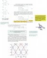
Please have a look here. In my view Vbn leads Van and also Vcn. Vbn has already completed 120 degrees of its cycle at t=0. Van is just starting its cycle at t=0. But Vcn is still short of 120 degrees to completes its cycle before it can start a new open.

Could you please guide me on that? Thank you.
 

Attachments

WBahn

Joined Mar 31, 2012
30,071
For this type of discussion, one waveform can lead or lag another waveform by no more than 180 degrees. If A leads B by 350 degrees, this is indistinguishable from A lagging B by 10 degrees.
 

Thread Starter

PG1995

Joined Apr 15, 2011
832
Thank you.

I agree with some part of what you said and disagree with the other part.

For this type of discussion, one waveform can lead or lag another waveform by no more than 180 degrees.
Conventionally (at least what I have seen in many physics textbooks) phase is determined by looking at upward displacement (crest is part of this upward displacement and the amplitude is at its maximum) and downward displacement (trough is part of this half cycle and the amplitude is at its minimum); crest and trough are 180 degrees apart. Let me elaborate. If we are comparing two waveforms, A and B. The x axis represents time and y axis amplitude. The upward displacement start at 0 degrees and ends at 180 degrees, and downward displacement starts at 180 degrees and ends at 360 degrees. Please have a look on the diagram below.


According to the 'convention', waveform A is said to be leading at time t=0, it's going thru its upward displacement half cycle. (Although in the diagram I've tried to show the crest, it wouldn't have mattered even if it was some some other part of upward displacement half cycle like 140 degrees). The waveform B is said to be lagging behind waveform B because at time t=0, it's going thru its downward displacement half cycle. When you say that "If A leads B by 350 degrees, this is indistinguishable from A lagging B by 10 degrees", I agree with you.

But considering this 'convention', phase sequences as they are stated doesn't make sense to me. Could you please help me? Thank you.

PS: Perhaps in three phase power analysis they use a little different 'convention'.
 

Attachments

Last edited:

WBahn

Joined Mar 31, 2012
30,071
Where the waveforms are at t=0 is irrelevant as to which is leading the other. There is nothing special about t=0. You can draw a vertical line to use as a reference wherever you would like.

Draw two sinusoids (of the same frequency) on the same time axis, but don't label the axis. Label the two waveforms A and B. Now draw a vertical line through some easily identifiable point on waveform A (the peak, the positive-going zero crossing, doesn't matter). Let's say that you use the peek. Now look at where B peeks relative to this. It will peak somewhere between where A reaches the trough before the line and where it reaches the trough after the line. If B peeks before A (i.e., to the left of the line), then A lags B. If B peeks after A, then A leads B.

It's that simple.

Notice that the definition for 3-phase polarity talks about it being positive if phase A leads phase B and phase B leads phase C.

Just write the order in which phases reach the same point in the waveform. Start from when A peeks. Which 0ne peeks next, B or C? which one peeks next after that? B or C. Write them in that order. You have your sequence identifier.
 

MrAl

Joined Jun 17, 2014
11,489
Hi,

The simple answer is the wave that comes first in time leads and the wave that comes next lags. It is easiest to look for a zero crossing to determine this, for the wave you want to call the reference wave.
In most power applications the phase "wraps around" so that 350 degrees lagging will be deemed 10 degrees leading because the assumption is steady state. In some other applications though we need to specify 350 degrees lagging. Since these questions are mostly about power line applications though i would ignore that for now.

I posted this picture in one of your other threads i am not sure if you missed it or not. The lead and lag relationship is shown here.
 

Attachments

Thread Starter

PG1995

Joined Apr 15, 2011
832
Hi again,

Please have a look here. Do you think that the connections shown for the three-phase Y and Delta sources are correct?

It's easier to conceptualize a Y source because it, in a way, could be thought as combination of three separate single phase generators assuming the frequency, phase and all other parameters are ideally the same. In a Y source no current would flow if nothing is connected to the source.

A Delta source is little difficult to conceptualize compared to a Y source. More importantly, one could incorrectly think that when nothing is connected to a Delta source, the current could flow between the windings because all the windings are interconnected. But as it is obviously when we look at the interference of individual voltage waveforms that the current cannot flow between the windings because overall voltage between the windings cancel out. Do you agree with this? Thank you.
 

Attachments

Last edited:
Top