Phase control dimmer for fan control

Thread Starter

ZweedNaat

Joined Feb 15, 2017
25
Hey guys,

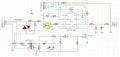
I've included a schematic. I found this schematic and want to use it for controlling a fan.
The thing is, I want to control the speed with an Arduino. So I figured that I could use this schematic and make the variable resistor using an Arduino and a FET to control the schematic.

But I am not quite sure how and what components to use. As of right now I have a DB3 DIAC I want to use and a BTA16-600 TRIAC. I also want to know if I need to use high power resistors.

I do not have a lot of experience when it comes to alternative current.

Thanks for the help in advance!
 

Attachments

MaxHeadRoom

Joined Jul 18, 2013
30,655
You need phase control using a random phase optocoupler such as the MOC301X series, see Fairchild AN-3006.
You also need a zero-crossing detect circuit.
There is also a few designs out there via Google for μp control.
Max.
 
Last edited:

DickCappels

Joined Aug 21, 2008
10,661
The resistor will see only a volt or so more than the diac voltage, which will usually be under 40 volts, so you can estimate the peak power in the resistor that way.

I suggest you put a resistor in series with the your random phase optocoupler so you can control the charging rate of the timing capacitor. If your optocopuler is a perfect switch the effective resistance, R' = R/D, where R is the value of the resistor and D is the duty cycle of the switch. Be sure to keep your PWM frequency low enough for the coupler to keep up.

For the optocoupler you might want to use one with a bipolar transistor as the output and put that in a full wave bridge so it only see DC, or use two couplers in parallel so each conducts on a different half cycle.

I tried the lamp dimmer approach, as have many others, but it produced an annoying buzzing sound. The two solutions that worked well -did not damage the motor or produce annoying noises were to use a Variac to reduce the voltage to the fan, and a cheaper solution was to put some motor-run capacitors in series with the fan motor to cut the total power about to half normal.
 

Janis59

Joined Aug 21, 2017
1,894
If this is not a high accuracy project but ONLY a bulb dimmer circuit what is as old as world, then latest I bought from China for 15 CENTS a piece for 25 Amp.... even triac costs much more.
You may see the implementation at www.electronics-tutorials.ws/power/power17.gif however the input filter via small ferrite core choke would be mandatory, and if You want not to loss a half of period then Gretz bridge too, as shown at http://masters.donntu.org/2008/kita/fesenko/images/ris1_ang.gif
Good implemented work for larger power looks like this: www.8085projects.info/wp-content/uploads/Variable%20speed%20high-power%20thyristor%20trigger%20circuit._thumb.jpg
however even simple implementation works well
https://upload.wikimedia.org/wikipe...g/200px-Lightdimmer_with_diode_bridge.svg.png

Yet if dislike the Gretz, one may shift to the triac intead of thyristor (and he will do good choice by this) like here (note the snubber along with triac, it have an important role and save a lot of money and time) www.next.gr/uploads/52/1200-watt-ac-dimmer-by-triac-q4006lt.jpg

BUT, if ARM is the goal not a dimming, better think about www.instructables.com/id/Arduino-controlled-light-dimmer-The-circuit/ what is so well explained there or alternatively http://www.instructables.com/id/AC-PWM-Dimmer-for-Arduino/

The first problems You may get when dimmer will realize the inductive load in the output. It dislike it. More worse if the word fan means indeed a fan such like stays at computer. There are ONLY two options how it can work as it always have an inner rpm stabilizer: `to go, or not to go, that is a question`. And no a grey zone between these two extremes. It is not regulable except if You extirpate and simulate the inner circuit but then how to open without not crash the plastics.
 
Last edited:

MaxHeadRoom

Joined Jul 18, 2013
30,655
I am assuming it is a shaded pole induction motor, I have done it with Picmicro control some of the methods in the Fairchild app note.
The basic manual version is also used for these fans.
Max.
 

Thread Starter

ZweedNaat

Joined Feb 15, 2017
25
If this is not a high accuracy project but ONLY a bulb dimmer circuit what is as old as world, then latest I bought from China for 15 CENTS a piece for 25 Amp.... even triac costs much more.
You may see the implementation at www.electronics-tutorials.ws/power/power17.gif however the input filter via small ferrite core choke would be mandatory, and if You want not to loss a half of period then Gretz bridge too, as shown at http://masters.donntu.org/2008/kita/fesenko/images/ris1_ang.gif
Good implemented work for larger power looks like this: www.8085projects.info/wp-content/uploads/Variable%20speed%20high-power%20thyristor%20trigger%20circuit._thumb.jpg
however even simple implementation works well
https://upload.wikimedia.org/wikipe...g/200px-Lightdimmer_with_diode_bridge.svg.png

Yet if dislike the Gretz, one may shift to the triac intead of thyristor (and he will do good choice by this) like here (note the snubber along with triac, it have an important role and save a lot of money and time) www.next.gr/uploads/52/1200-watt-ac-dimmer-by-triac-q4006lt.jpg

BUT, if ARM is the goal not a dimming, better think about www.instructables.com/id/Arduino-controlled-light-dimmer-The-circuit/ what is so well explained there or alternatively http://www.instructables.com/id/AC-PWM-Dimmer-for-Arduino/

The first problems You may get when dimmer will realize the inductive load in the output. It dislike it. More worse if the word fan means indeed a fan such like stays at computer. There are ONLY two options how it can work as it always have an inner rpm stabilizer: `to go, or not to go, that is a question`. And no a grey zone between these two extremes. It is not regulable except if You extirpate and simulate the inner circuit but then how to open without not crash the plastics.
Hey!

Especially the instructables links you sent me look good.

The thing is. I want to control a inductive fan with a circuit like this. I'm not sure if that is possible. As stated above I have a view components lying around and I kind of want to use those components. I can order other extra components, but I alreaady have those here so might as well use them. Should be possible. Just not know how exactly.

The TRIAC I have (BTA16-600) is snubberless. I also did a few tests with it. I made a SSR basically and it worked like a charm. The next step is to control fan speed.

For what it's worth the code for the fan FCDDC 241-241. The input power is 1255W

Can you give the MOC3021 (which I also have here) PWM which then feeds it into the triac? Won't the triac get really hot?
 
Last edited:

Thread Starter

ZweedNaat

Joined Feb 15, 2017
25
Last edited:

Thread Starter

ZweedNaat

Joined Feb 15, 2017
25
The resistor will see only a volt or so more than the diac voltage, which will usually be under 40 volts, so you can estimate the peak power in the resistor that way.

I suggest you put a resistor in series with the your random phase optocoupler so you can control the charging rate of the timing capacitor. If your optocopuler is a perfect switch the effective resistance, R' = R/D, where R is the value of the resistor and D is the duty cycle of the switch. Be sure to keep your PWM frequency low enough for the coupler to keep up.

For the optocoupler you might want to use one with a bipolar transistor as the output and put that in a full wave bridge so it only see DC, or use two couplers in parallel so each conducts on a different half cycle.

I tried the lamp dimmer approach, as have many others, but it produced an annoying buzzing sound. The two solutions that worked well -did not damage the motor or produce annoying noises were to use a Variac to reduce the voltage to the fan, and a cheaper solution was to put some motor-run capacitors in series with the fan motor to cut the total power about to half normal.
Thanks for your reaction!

If my math is correct I can do with a little higher than 0,5W resistor. Can you do something with the information in the reply to Janis59?
Because I kind of want to use a circuit like the attachment in the very first post.

Also I've added an attachment of the SSR I was talking about that I made and worked really well. Only used a BTA16 instead of a BTA24 because my fan will not take more than 8 amps approx. The starting current is just a little higher I think.TRIAC schakeling.png
 

DickCappels

Joined Aug 21, 2008
10,661
One hitch: you cannot get PWM through a triac output coupler. If you want to control the lamp dimmer curcuit that uses a diac you will need to use a coupler with a transistor output.

You can use your MOC3021 with the technique shown in the application note that MaxHeadroom provided.
 

Thread Starter

ZweedNaat

Joined Feb 15, 2017
25
One hitch: you cannot get PWM through a triac output coupler. If you want to control the lamp dimmer curcuit that uses a diac you will need to use a coupler with a transistor output.

You can use your MOC3021 with the technique shown in the application note that MaxHeadroom provided.
Okay, good to know.

So lets say I use the MOC3021 the way they do in the appnote. VR1 is used to change where the phase cutting comes in to place, right?
How will I use my Arduino to turn VR1?

I'm missing the link between phase control and doing that with the Arduino.
 

DickCappels

Joined Aug 21, 2008
10,661
You want to get this:
upload_2017-9-14_19-19-3.png


To know when to turn on the triac, you have to have a signal that tell your controller when a half cycle has started. With the circuit below, the outputs of both optocouplers go "open circuit" around the zero crossing, so if the emitters were grounded and the collectors had a pullup (20k should be good) you would get a short positive going pulse at the zero crossing.

upload_2017-9-14_19-27-56.png
Now your controller knows when each half cycle starts, then all it has to do is wait (set a timer, enter a loop, whatever your favorite timing method) and turn on the triac at the appropriate phase.

upload_2017-9-14_19-23-0.png
 

Thread Starter

ZweedNaat

Joined Feb 15, 2017
25
Here is the one I put together for the Picmicro, you can use a small mains transformer or as in the 3009 App for isolation of the zero crossing detection.
There is another shown here also, http://alfadex.com/2014/02/dimming-230v-ac-with-arduino-2/
Max.
This looks very promissing!

Give me a week or so and I will try to come up with something like this you sent. I'll share the schematics if I come up with something.
If I have any more questions I'll ask them.

Thanks so far everybody!
 

Janis59

Joined Aug 21, 2017
1,894
RE:""Won't the triac get really hot?""
Always get, the basic question is how much hot.
And here You may use a thumbrule 2 Volt*current=Watts or in Your case 2*10 Amp=20W. As it is more than sure that TO220 cannot cool so much by own surface, You`ll need around 20 cm2 of rib total area, 10 cm2 each side. Thus 2,5x4 cm aluminium platelet will be enough, or smaller with few ribs.
 

Thread Starter

ZweedNaat

Joined Feb 15, 2017
25
Okay guys, as promissed I am back and I have tried a few things.

The schematic I attached is the one I tought would work. I got it from the link MaxHeadRoom sent. Thanks for that! It really looked promissing. So I built that on a breadboard in a simillar way as the author of that article did. Well, what happened next was I bit of a surprise. Since I triple checked if the schematic was connected the right way.

Both 30k resistors just exploded, as well as the zero crossing optocoupler. To be completely fair I changed the 30k resistors to 47K resistors. nd I didn't use the 4N25 opto. Instead I used a CNY17, because I had one lying around. I checked both data sheets and they seemed very similar. Maybe I missed something.

A schematic like this is exactly what I am looking for.
 

Attachments

DickCappels

Joined Aug 21, 2008
10,661
If it were built correctly each resistor would dissipate 100% of its rating. That would shorten the life of the resistors, not make that part of the circuit explode.

It is possible that something was connected incorrectly but it is more likely that the resistors were the wrong value, like 30 Ohms instead
Os 30 K.

The circuit looks fine on paper, but many of us would put a 1 K resistor from the triac gate to MT1.
 

Thread Starter

ZweedNaat

Joined Feb 15, 2017
25
If it were built correctly each resistor would dissipate 100% of its rating. That would shorten the life of the resistors, not make that part of the circuit explode.

It is possible that something was connected incorrectly but it is more likely that the resistors were the wrong value, like 30 Ohms instead
Os 30 K.

The circuit looks fine on paper, but many of us would put a 1 K resistor from the triac gate to MT1.
Well, thats what I tought as well. I'm quite sure that those resistors where 47k that I picked. Let's say those resistors weren't 0.5 Watts what would happen then?

It's weird to me because only that past of the circuit lit itself on fire. The bridge rectifier didn't. Also the CNY17 that I used died as well. Is it possible I connected the BR wrong?
 
Top