 Facebook
 Google
 GitHub
 Linkedin
Hi,
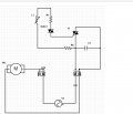
I am trying to learn and understand the basics of motor speed controllers ,I have a number of faulty PCBs from a small rotary pendant style drill.(see pics / the circuit diagram was drawn by me so hoping it’s nearly correct )
I have started testing these and found that with no load the controller is showing full AC output ,although as soon as you place a load on the controller the AC output instantly disappears ?
I have looked online and got a little confused with testing triacs , I have order some new triacs,
I would very much welcome any suggestions or help on how to test or fault find ,
Thank you Darren.
Attachments
-
 159.9 KB Views: 11
 -
 188.7 KB Views: 8


