Facebook
 Google
 GitHub
 Linkedin
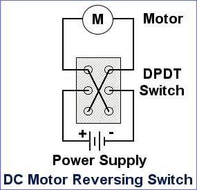
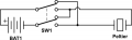
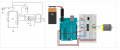
I used an h-bridge to reverse the current of a peltier plate, which was the same as this video
.
In the video, he had to physically remove a wire and place it somewhere else to reverse the current of a peltier plate. I was wondering how would I do it without removing a wire?
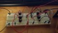
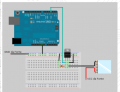
Also how do I control the current flow with an Arduino? In the image I provided, I figured out how to control the current with just the peltier itself without reversing current or anything
Would the circuit for the DC motor controlled by a L293NE h-bridge work if I just replace the DC motor with the peltier plate?
Source: https://itp.nyu.edu/physcomp/labs/motors-and-transistors/dc-motor-control-using-an-h-bridge/
In the video, he had to physically remove a wire and place it somewhere else to reverse the current of a peltier plate. I was wondering how would I do it without removing a wire?
Also how do I control the current flow with an Arduino? In the image I provided, I figured out how to control the current with just the peltier itself without reversing current or anything
Would the circuit for the DC motor controlled by a L293NE h-bridge work if I just replace the DC motor with the peltier plate?
Source: https://itp.nyu.edu/physcomp/labs/motors-and-transistors/dc-motor-control-using-an-h-bridge/
Attachments
-
 82.1 KB Views: 40
 -
 75.6 KB Views: 45