 Facebook
 Google
 GitHub
 Linkedin
G'day!
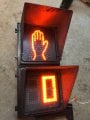
I found a crosswalk LED display and I'd like to set it up in my workshop. Unfortunately I don't have the technical knowhow to do this, and I can't find anything on the Net.
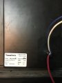
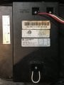
The LEDs work, but I get a constant "0" (zero) on the bottom display and the "Do not walk" hand on the upper when I simply connect the leads to a 120 outlet. No countdowns, no blinking. The two LED casings are sealed, the wiring is ultra simple. So what controls the timer? Is there a missing component? Can I hack this to get it blinking and counting in all its glory?
Any ideas?
Thanks!
I found a crosswalk LED display and I'd like to set it up in my workshop. Unfortunately I don't have the technical knowhow to do this, and I can't find anything on the Net.
The LEDs work, but I get a constant "0" (zero) on the bottom display and the "Do not walk" hand on the upper when I simply connect the leads to a 120 outlet. No countdowns, no blinking. The two LED casings are sealed, the wiring is ultra simple. So what controls the timer? Is there a missing component? Can I hack this to get it blinking and counting in all its glory?
Any ideas?
Thanks!
Attachments
-
 195.9 KB Views: 27
 -
 209.9 KB Views: 36
 -
 124.5 KB Views: 32
 -
 237.6 KB Views: 35
 -
 167.9 KB Views: 37
")


