PCB from a TV - button acting as though it's depressed, yet isn't

Thread Starter

nathanking

Joined Apr 23, 2018
14
Hello everyone!

I'm fairly new to electronics and I'm trying to fix a tv and stop it automatically going down in channels.

The problem seemed simple, the channel down button on the tv is acting as if it it is depressed. Yet physically it's not. You can push it and it depresses, like normal. Yet, once the PCB is inserted into the tv, without touching anything, the channels start going down.

I used a mini compressor to blow out any dirt particles from all over the PCB, especially that button.
I've replaced the button, thinking it was somehow dirty or faulty. It changed nothing.
I've cleaned the entire PCB.
I've looked over the PCB and can see no issues.

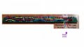
I've taken a couple of photos, the problematic button is the one with black ink near it.

I'd love some suggestions on how I can fix this issue.

Thank you.
 

Attachments

autotuner

Joined Oct 2, 2012
8
Hello everyone!

I'm fairly new to electronics and I'm trying to fix a tv and stop it automatically going down in channels.

The problem seemed simple, the channel down button on the tv is acting as if it it is depressed. Yet physically it's not. You can push it and it depresses, like normal. Yet, once the PCB is inserted into the tv, without touching anything, the channels start going down.

I used a mini compressor to blow out any dirt particles from all over the PCB, especially that button.
I've replaced the button, thinking it was somehow dirty or faulty. It changed nothing.
I've cleaned the entire PCB.
I've looked over the PCB and can see no issues.

I've taken a couple of photos, the problematic button is the one with black ink near it.

I'd love some suggestions on how I can fix this issue.

Thank you.
A couple of this.
If you remove the switch altogether what happens?
And
Are you sure the new switch is oriented correctly? Could be 90 degrees out of whack. Most of those sorts of switches are really only 2 poles even though they have 4 legs.
 

Thread Starter

nathanking

Joined Apr 23, 2018
14
A couple of this.
If you remove the switch altogether what happens?
And
Are you sure the new switch is oriented correctly? Could be 90 degrees out of whack. Most of those sorts of switches are really only 2 poles even though they have 4 legs.
Thanks for you reply and suggestions.

The old switch was the original, therefore the poles wouldn't an issue as it would never have functioned correctly.
What could removing the switch prove? Unsure of your logic as I replaced the switch with a new one.
 

dendad

Joined Feb 20, 2016
4,637
Try measuring across the switch with a multimeter on OHMs. And see if it changes when pushed. Compare it to the other switches.
 

MisterBill2

Joined Jan 23, 2018
27,447
The first thingto check is to see if the other switches are normally open or normally closed. If you replaced a normally closed switch with a normally open one then of course it will constantly change. It may also be that one of those small devices on the board has failed. Trace out the circuit and the problem may be easy to see, since the connector terminal functions are already on the top of the board. If you have an ohm meter you can connect to the connector and see what each button does, or does not do.
 

LesJones

Joined Jan 8, 2017
4,511
I have partialy traced out the schematic of the board. I have called the switches S1 to S7 starting at the left hand end and counted the resistors R1 to R6 starting at the left hand end. I think S7 just shorts two pins on the connector. the other 6 switches are in two groups of 3. If you measure the resistance across S6 the reading should be the sum of R4, R5 and R6 when no switch is pressed. With S4 pressed the resistance across S6 should be the sum of R5 and R6. With S5 pressed the resistance across S6 should be the value of R6. With S6 pressed the resistance across R6 should be zero. S1 to S3 are connected in a similar way. I assume S4 was the faulty switch. Post the values of the resistors and the resistance readings across S6 With no switch pressed, with S4 pressed, with S5 pressed and with S6 pressed. The reasoning behind "autotuner's" comment in post #2 is that the original switch had failed short circuit but when you fitted a new switch you fitted it rotated by 90 Deg.

Les.
 
Last edited:

Tonyr1084

Joined Sep 24, 2015
9,744
Assuming the problem existed before you changed the switch and still is manifesting the problem then the conclusion would be that there's a short somewhere. Could be on the switch board, could be in the connecting cable. Could even be on the board the switch board is connected to.

What was suggested was to remove the switch and operate the television without the switch there at all. What this would prove is whether the problem was at the switch or if it were elsewhere.

Switching channels is likely controlled by a microprocessor. At some pin (or pins) input, a signal will command a channel change, be it up or down. Volume and whatever else those buttons control, all would be connected to a microprocessor. It's possible the processor has gone bad. One would assume this because before the problem manifested itself, everything was working normally. But as I mentioned, there could be shorts caused by a number of things. In the connectors, it's possible that when they were terminated there may have been a stray wire strand making contact where it ought not. This is not a common problem, but certainly one worth looking for. Another problem could be a solder ball has come lose from somewhere on the board and may have lodged itself between two pins of the microprocessor. OR it's possible that excess solder has presented a near short. Under clean conditions it doesn't present a connection. But if whiskers start to grow then it's possible a short has developed. Tin Whiskers is an interesting phenomena that CAN cause latent failures such as the one your experiencing. A simple cleaning with a stiff brush like a toothbrush can clean the problem away. OR flux that has become contaminated and conductive could also result in an errant signal making its way to where it's not wanted.

There can be several reasons why your TV is scrolling down through the channels. For starters I'd give it a good cleaning. Then I'd inspect for shorts such as a stray wire on a connector or a solder ball or solder bridge on a microprocessor. But don't forget the possibility the processor has just gone bad. It happens.
 

mcgyvr

Joined Oct 15, 2009
5,394
If the TV is turned on without that board in place what happens? That can help narrow down the problem..
Besides the beginner solder joints that board looks just fine from here..

Have you also removed the batteries in the remote control if there is one to ensure the problem isn't with that?
Or your dog watching you repair all this sitting on the remote button :)
 

Tonyr1084

Joined Sep 24, 2015
9,744
Have you also removed the batteries in the remote control if there is one to ensure the problem isn't with that?
Or your dog watching you repair all this sitting on the remote button :)
OH YES! Very real possibility. And funny too because the wife sets her books on top of the remote then can't understand why the TV is doing weird things when nobody wants it to. But you don't need to remove the batteries, just make sure it's not able to be seen by the TV. Putting a towel over it will do.
 

Thread Starter

nathanking

Joined Apr 23, 2018
14
Hello everyone!

I'm fairly new to electronics and I'm trying to fix a tv and stop it automatically going down in channels.

The problem seemed simple, the channel down button on the tv is acting as if it it is depressed. Yet physically it's not. You can push it and it depresses, like normal. Yet, once the PCB is inserted into the tv, without touching anything, the channels start going down.

I used a mini compressor to blow out any dirt particles from all over the PCB, especially that button.
I've replaced the button, thinking it was somehow dirty or faulty. It changed nothing.
I've cleaned the entire PCB.
I've looked over the PCB and can see no issues.

I've taken a couple of photos, the problematic button is the one with black ink near it.

I'd love some suggestions on how I can fix this issue.

Thank you.
Hello everyone.

Many thanks for your responses. It has given me a few ideas and tests to perform.
I neglected to mention that the scrolling problem isn't present when I disconnect the problem PCB from the tv. It doesn't automatically control. Which is the main reason I think the problem lies in this particular PCB.

I've now bought some contact cleaner - In the possibility that the cleaner I used didn't do the trick. No change.

I used the multimeter and tested the board.
I tested each of the resistors, which had the following readings from right to left of the board (where the connector is on the left.
1.16 678 464 1.21 675 469
I tested each of the buttons, which had the following readings from right to left of the board (where the connector is on the left.
1.18 1.86 2.32 1.2 1.88 2.33
Each of the above buttons readings went down to zero when the button was depressed.
The final button, to the left of the connector, the power button. Well, it seemed that my multimeter didn't go up high enough for it, it didn't want to get a reading. However, when the button was depressed the readings lowered down to zero.

There is no remote control - but that would have been very funny - eventually :)

Any suggestions will be gratefully received.

Thanks again.
 

LesJones

Joined Jan 8, 2017
4,511
As you have only given numbers without units I am guesseing that when you show numbers like 1.88 the units are K ohms. and when you give numbers like 469 the units are ohms. I don't think there is a fault with the board as the readings add up as expected from the part schematic I traced out. (The resistors will be the standard values of 1.2K ohms, 680 ohms, and 470 ohms.) I will post the part schematic later when I have time.

Les.
 

Thread Starter

nathanking

Joined Apr 23, 2018
14
As you have only given numbers without units I am guesseing that when you show numbers like 1.88 the units are K ohms. and when you give numbers like 469 the units are ohms. I don't think there is a fault with the board as the readings add up as expected from the part schematic I traced out. (The resistors will be the standard values of 1.2K ohms, 680 ohms, and 470 ohms.) I will post the part schematic later when I have time.

Les.
Absolutely Les, thanks for your reply. I should have been a little more specific.

Somehow, there is clearly a fault with this PCB.... Unless, as it occurs to me, is it possible that somehow the receiving circuit is specifically faulty to that button or range in ohms?
 

Tonyr1084

Joined Sep 24, 2015
9,744
You may well be correct in assuming the board is the fault in your circuit. However, since each button shorts out its resistor, except for the power button, the problem may still lie within the microprocessor.

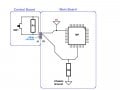
Assuming the affected circuit, when the button is not being pressed, presents 470Ω and 0Ω when pressed, I would assume there is a voltage potential at the particular pin on the microprocessor. If you press the button you apply (assumed) full voltage (whatever that may be) which signals the MP (microprocessor) to scroll the channels. The resistor (whichever one it is) may form part of a voltage divider. If the other half of that divider has become disconnected (i.e. bad solder joint or failed component, likely another resistor) then that can account for the lack of the problem when the board is disconnected from the circuit. I'll bang out a quick drawing in a few and post it. But keep in mind, this is just guesswork.
 

Tonyr1084

Joined Sep 24, 2015
9,744
Here's my theory: The main board provides power (5 volts likely) to several components. Among them, your circuit. In my illustration below, power is fed to R1 through the connectors J1 & P1. (Resistor numbers will likely be different) Power flows through R1 and to R2 and the MicroProcessor (MP). R2 holds pin #26 (my illustration), holding pin 26 to some voltage below 5 volts. R1 & R2 form a voltage divider. The MP sees a low voltage, not ground, and does not change the channels. When you push SW1 you provide full 5 volts to pin #26 and the MP scrolls through the channels as intended. If the chassis ground at R2 is bad (not connected, i.e. bad solder joint or R2 is bad) then the MP will always see a full 5 volts and will continue to scroll. When you disconnect the control board you remove the 5 volts from pin #26 and the channels do not scroll. So my theory is that you do not have a bad control board, nor would I think the connecting cable (not shown) is likewise good. However, don't assume it is good, check it. But don't expect to find it bad.

I think the problem is not in the control board but on the main board somewhere.

TV Control.jpg
 

Tonyr1084

Joined Sep 24, 2015
9,744
Since there are seven buttons but only four wires making the final connections I'd guess that the different values of resistance is being read by the MP. There are only four lines but there are three different resistor values. Since I don't know the functions of the other buttons, I'd guess 2 buttons to control the channels, 2 buttons to control volume, 1 button for power on and off and the other two buttons may be for programming. It appears the power button simply cycles the on/off function, so only two wires needed for that. The power to the board is common (it looks like) to all the switches and resistors, so the other two lines are for control and for programming. At least that's what I conclude from what limited access to the board I have. Someone said they're doing a schematic of the board, that may prove useful to us in deciphering what's going on.

Hope this helps.
 

LesJones

Joined Jan 8, 2017
4,511
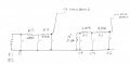
This is the part of the schematic I have traced out.
260418.jpg

I suspect the common of all the switces connects to the gnd pin on the connector. I think the switch to the right of the connector just shorts the pwr pin to ground. I agree with the way Tony suggests that it works but it has a pull up resistor rather than a pull down resistor. As both groups of 3 switches are the same I think the inpuit circuit for each one will be the same. I suggest with the board connected to the TV and powered up measuring the voltage between gnd and pin key 0. do this with no buttons pressed then in turn pressing buttons 1, 2, 3 (Counting from the left.) These readings should be the correct readings. (Unless the fault is effecting both groups of three buttons.) Repeat this test measuring from ground to tke key 1 on the connector bit pressing buttons 4,5,6. Post the results. Please use units not just numbers as you did with your resistance readings. (Had I guessed right for the units or was the 1.2 megohms ? )

Les.
 

MisterBill2

Joined Jan 23, 2018
27,447
One more suggestion based on nothing so far having solved the problem, and that is examine the board for a hairline crack in a trace. Then examine the solder joints for hairline, or much finer, cracks. And as the resistors have markings, compare the marked value with the measured value. One or more may not be right.
 
Top