Pcb fault for a Noob

Thread Starter

LeeUK

Joined Jul 1, 2024
14
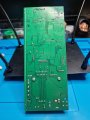
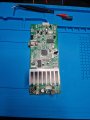
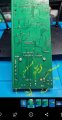
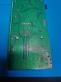
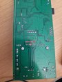
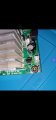
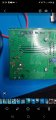
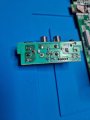
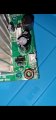
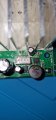
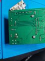
Iv reciently got into fault finding and decided to work on my mothers radio/cd juke box which suddenly stopped powering on, it takes a 12v 2a into a board which then connects too another pcb via 2pin connector, i get 12v passing through the power board untill i connect the 2nd board my voltage then drops to 0.3, as far as im aware iv tested a good chunk of components around the area but having no joy... ill attach pictures of the board and any ideas would be appreciated ‍♂ (my soldering still isnt the best ) iv replaced the 100uf compacitor, the 3pin power transistor & ldo regulator, i cant see any other issues and dont seem to be able to find any other shorts, any help would be massive, cheers
 

Attachments

dl324

Joined Mar 30, 2015
18,216
Welcome to AAC!

Are you able to trace the "2nd board" (not a very descriptive term) to make a schematic?
iv replaced the 100uf compacitor, the 3pin power transistor & ldo regulator
What was your reasoning for replacing them?

Guessing isn't a very good troubleshooting method; though I've known electronic technicians who used that method. One guy used what he called the "quadrant method" - he replaced all of the components in a quarter of the board and continued until he "fixed" it. If that didn't work, he marked the board a "dog" and put the board back for someone else to use. Unless he caused enough damage to the board that he could scrap it.
 

Thread Starter

LeeUK

Joined Jul 1, 2024
14
Appreciate the reply first of all this was my last hope , to be completely honest im no good at schematics but ill try mark up the components on the second pcb for you, i replaced them as i made the mistake of testing the components using my multimeter while they was still in the board too later realise the values arnt always correct, once i removed them they was actually ok but as i already purchced the new ones just replaced them anyway haha ‍♂ the 2nd board has a fair chunk of components so i have only really examined the components around the main entrance of the power rail
 

Attachments

MrChips

Joined Oct 2, 2009
34,626
Testing components and replacing components at random is taking shots in the dark. This is not a good trouble-shooting technique. You have to learn how to be an electronics detective. The more you do it, the easier it becomes.

Firstly, you need to acquire electronics fundamentals. Learn how all components work, what they do and how they are applied in a circuit. Next, learn how you use building blocks to create a complete system. Learn functionality - what functions are required to have a working system.

Then try to apply this knowledge to your trouble-shooting techniques. Look at symptoms and clues.
Try to use reasoning.
If supply voltage falls when load is applied, this could mean that the load is drawing too much current.
Be careful that you don't make false assumptions. It could also mean that the power supply is faulty; it is unable to supply the required current. So you have to identify which of the two is at fault, the PSU or the load? Find a way to check the two separately in terms of current capacity and load current.
 

Thread Starter

LeeUK

Joined Jul 1, 2024
14
I should add aswell iv tried the fault
Testing components and replacing components at random is taking shots in the dark. This is not a good trouble-shooting technique. You have to learn how to be an electronics detective. The more you do it, the easier it becomes.

Firstly, you need to acquire electronics fundamentals. Learn how all components work, what they do and how they are applied in a circuit. Next, learn how you use building blocks to create a completer system. Learn functionality - what functions are required to have a working system.

Then try to apply this knowledge to your trouble-shooting techniques. Look at symptoms and clues.
Try to use reasoning.
If supply voltage falls when load is applied, this could mean that the load is drawing too much current.
Be careful that you don't make false assumptions. It could also mean that the power supply is faulty; it is unable to supply the require current. So you have to identify which of the two is at fault, the PSU or the load?
Thanks alot for the response, i appreciate all that im constantly researching and i have some practice boards iv been working on, thid has just through a spanner in the works for me haha, with power reaching the 2pin connector at 12v and dropping only when i connect the 2nd PCB i thought this would cancel out it being the power supply, thats why iv put most of my attention to the 2nd pcb as it seems to drop voltage only once thats connected
 

MisterBill2

Joined Jan 23, 2018
27,159
Many times when there is a sudden total failure the problem is a failed connection, or even a failed motion part in a switch. So often the first step would be a close examination with good lighting.

The very best "professional" method is to understand how the system works and what it is supposed to do, then learn what it is doing instead. This will usually point towards the failed element. No, this is not simple nor quick to pick up. And it does require a great deal of insight and experience. BUT it has resulted in the resurrection of quite a few items that were diagnosed as "not repairable." Which was partly true, in that the person messing with them was in fact incapable of discovering the problem or repairing it once the problem was known.
 

narkeleptk

Joined Mar 11, 2019
586
It sounds like you have a short on board 2 since voltage is dropping. Research voltage injection technique for finding short circuits.
 

LesJones

Joined Jan 8, 2017
4,511
Does the 12 volts at the INPUT to boad 1 drop when board 1 is connected to board 2 ?
Have you measured the resistance between the input pins on board 2 ?
I think the input part of board 2 possibly contains a switching regulator. You picture is not good enough to read the part number of the 8 pin IC. This may be a switch mode regulator IC. It looks like there may be a blob of solder between the collector pin and one of the other 2 pins of the TO220 transistor. Have you tested this transistor for a collector - emitter short ?

Les.
 

Thread Starter

LeeUK

Joined Jul 1, 2024
14
Does the 12 volts at the INPUT to boad 1 drop when board 1 is connected to board 2 ?
Have you measured the resistance between the input pins on board 2 ?
I think the input part of board 2 possibly contains a switching regulator. You picture is not good enough to read the part number of the 8 pin IC. This may be a switch mode regulator IC. It looks like there may be a blob of solder between the collector pin and one of the other 2 pins of the TO220 transistor. Have you tested this transistor for a collector - emitter short ?

Les.
Hi les, yes once i connect board 2 the voltage drops at both points, at the adapter entry and at the 2 pin connector output, i even checked the voltage at the end of the 2pin connector and ots outputtinf 12v untill i connect it to yhe 2nd board then everything drops, i actually thought itn as the 8pin as i tried the freeze method and that heated up pretty much instantly so i changed that out it was a 'TD1509p5 semiconductor' i think the blob of solder is just the bad picture aswell as theirs nothing their, iv tested for shorts across the transistor too ‍♂ haha
 

LesJones

Joined Jan 8, 2017
4,511
Befor I replaced the TD1509p5 I would have broken the 12 volt feed to it's input by unsoldering pin 1 to see if the short was related to that IC or components after it drawing too much current on the 5 volt rail. It is possible that the diode between its output (Pin2) and ground (Pins 5,6,7,8)could have failed short circuit. Measure the resistance of this diode to see if it is shorted.
The next thing I would suspect of loading the 12 volt rail is the audio amplifier IC. I would NOT replace it ath this stage. I would cut the tracks (At a point that is easy to repair.) that take the +12 volts to this IC. You will find which pins they are from the data sheet.
I suspect some of the 4 parallel tracks under the heat sink carry the +12 to this IC. (Identify them with resistance checks fron the +12v input to these tracks.)

Les.
 

Thread Starter

LeeUK

Joined Jul 1, 2024
14
Befor I replaced the TD1509p5 I would have broken the 12 volt feed to it's input by unsoldering pin 1 to see if the short was related to that IC or components after it drawing too much current on the 5 volt rail. It is possible that the diode between its output (Pin2) and ground (Pins 5,6,7,8)could have failed short circuit. Measure the resistance of this diode to see if it is shorted.
The next thing I would suspect of loading the 12 volt rail is the audio amplifier IC. I would NOT replace it ath this stage. I would cut the tracks (At a point that is easy to repair.) that take the +12 volts to this IC. You will find which pins they are from the data sheet.
I suspect some of the 4 parallel tracks under the heat sink carry the +12 to this IC. (Identify them with resistance checks fron the +12v input to these tracks.)

Les.
Cheers for the reply again, got back late from work so havnt had a chance to check today but i managed to do a quick resistance check and i found what pins run from the 12v, im going to try desolder pin 1 from the 12v tomorrow and see what im getting, just curious once i desolder pin1 and connect it back up and push the 12v what am i looking for and where am i checking? Thanks

Lee
 

LesJones

Joined Jan 8, 2017
4,511
What you are doing is to find where the +12 volts goes to and then disconnect it from each part that takes current directly from it. When you told me the part number of the 8 pin IC was TD1509p5 the datasheet confirmed my suspicion that it was a switch mode regulator dropping the 12 volts down to 5 volts for the logic ICs. From the data sheet I knew that pin 1 was the input. So disconnecting that would show if that was shorting out the 12 volts.
It is almost certain that the audio power amplifier IC will be powered directly from 12 volts so that is the next thing I would eliminate. (After that you would have to follow the tracks to see where else it connects to.) The audio amp will be the large IC on the heat sink. Again if you cut the track taking 12 vots to that IC and the 12 volts is no longer shorted out then that IC will be the fault. You need to be sure that the track that you cut ONLY goes to that IC. (There may be 2 power pins on the IC as it is probably stereo.)
The best way to fault find is get evidence that a component is faulty before replacing it.
One thing I should have asked is if it is the original power supply and if you have tested it with another load with a similar current consumption to the device you are trying to repair.

Les.
 

Thread Starter

LeeUK

Joined Jul 1, 2024
14
What you are doing is to find where the +12 volts goes to and then disconnect it from each part that takes current directly from it. When you told me the part number of the 8 pin IC was TD1509p5 the datasheet confirmed my suspicion that it was a switch mode regulator dropping the 12 volts down to 5 volts for the logic ICs. From the data sheet I knew that pin 1 was the input. So disconnecting that would show if that was shorting out the 12 volts.
It is almost certain that the audio power amplifier IC will be powered directly from 12 volts so that is the next thing I would eliminate. (After that you would have to follow the tracks to see where else it connects to.) The audio amp will be the large IC on the heat sink. Again if you cut the track taking 12 vots to that IC and the 12 volts is no longer shorted out then that IC will be the fault. You need to be sure that the track that you cut ONLY goes to that IC. (There may be 2 power pins on the IC as it is probably stereo.)
The best way to fault find is get evidence that a component is faulty before replacing it.
One thing I should have asked is if it is the original power supply and if you have tested it with another load with a similar current consumption to the device you are trying to repair.

Les.
Right ok great, well iv just tested resistance and your right theirs 2 pins that have continuity to the + pin of the 12v so i persume thats where the rail is, they both seem to be on the same rail coming down to the 12v so woult i just cut it where iv marked in blue? And send the 12v back through and see if it still shorts?
Also yes iv only used the main power supply iv tried no others. Appreciate the feedback again


Lee
 

Attachments

LesJones

Joined Jan 8, 2017
4,511
Yes that is a good place to cut the track. If that does clear the short make sure that the track does not continue on the component side to feed something else. To repair the cut track you will have to scrape off the solder resist coating to get to clean copper.

Les.
 

Thread Starter

LeeUK

Joined Jul 1, 2024
14
Yes that is a good place to cut the track. If that does clear the short make sure that the track does not continue on the component side to feed something else. To repair the cut track you will have to scrape off the solder resist coating to get to clean copper.

Les.
Great thanks, just rechecked before cutting the trace (good job i did) the picture i sent showing the pins that had continuity was the negative pin, the positive pin has continuity to the same 2 pins but also another 2 iv shown in the picture, could these 2 be sending the 12v through to another part of the board? And will i still be ok cutting where iv marked to cancel out it being the audio IC? Cheers
 

Attachments

LesJones

Joined Jan 8, 2017
4,511
As there is a short between + 12 volts and ground your meter will show continuity between them. Check which pins on the audio amplifier are the positive supply by looking at the datasheet. (Or visually follow the track.) The datasheet will be the easiest.

Les.
 

Thread Starter

LeeUK

Joined Jul 1, 2024
14
Could never find the datasheet for it to be honest, iv just traced the first pins i mentiond on both sides of the board and looks like they make their way to the power line, iv marked the track on the front on back where they lead too
Cut the line and lost all power to them pins & power is still shorting ‍♂ this board is becoming a nightmare haha
 
Top