Facebook
 Google
 GitHub
 Linkedin
Hello,
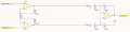
I have an analog differential signal. This signal has to be transported over a 20cm PCB trace.
I want to place the instrumentation amplifier near the analog differential signal and than transport the analog signal (0..3.3V) over the PCB.
To minimize (EMC) influence from outside, what is the best practice for:
1. Trace width (wide or small)
2. Ground plane offset distance
Thanks.