PCB design audio split

Thread Starter

Chrissalberts

Joined Jan 9, 2024
6
Hi there!

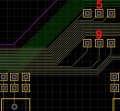
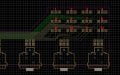
I have designed a pcb for a passive audio split but I'm wondering if this will work out or if it will give issues. Gerber file is included. I would solder an XLR connector to the pcb, and it'd split to two patch points right besides the connector going through over inner layer copper lines (so far so good I would assume) but I also have them go all the way to the side. The copper lines are close to eachother because it wouldn't fit otherwise (or I have to use 6 layers but then they're still close to eachother). Would love if someone could have a look and tell me if I'm making a big mistake, for example by putting the copper lines too close to each other, or if the lines are too long perhaps.

Thanks!
Chris
 

Attachments

Ya’akov

Joined Jan 27, 2019
10,226
Welcome to AAC.

You should post images rather than raw Gerber files. You are unlikely to get many people willing to jump the first hurdle of downloading, unzipping, and viewing your PCB.
 

Thread Starter

Chrissalberts

Joined Jan 9, 2024
6
Welcome to AAC.

You should post images rather than raw Gerber files. You are unlikely to get many people willing to jump the first hurdle of downloading, unzipping, and viewing your PCB.
Fair enough! I have included 3 screenshots, one of the full design, one more zoomed in and one even more zoomed in.

Thanks!

EDIT: the PCB is 436 x 62.5 mm
 

Attachments

MisterBill2

Joined Jan 23, 2018
27,186
From what I could see there is no problem. But a six layer PCB seems like way more than is needed. Double sided has always been adequate for all non-processor designs of mine. What are all the RJ11 connectors for??? I have a few digital audio teleconferencing mics that I have no clue about how to interface. Do not want to hijach the thread but I would want to find out how.
 

Thread Starter

Chrissalberts

Joined Jan 9, 2024
6
From what I could see there is no problem. But a six layer PCB seems like way more than is needed. Double sided has always been adequate for all non-processor designs of mine. What are all the RJ11 connectors for??? I have a few digital audio teleconferencing mics that I have no clue about how to interface. Do not want to hijach the thread but I would want to find out how.
Thanks for your response!! I have since updated the pcb. The top and bottom layers are just copper now. I use the 2 inner layers so the top and bottom can function as a "faraday cage" blocking RF interference. I'm not sure where you see RJ11 connectors. It's simply a passive "cold" split. I solder an XLR to the pcb and the 3 legs hard split to three different contacts on the board to which I solder shielded xlr cable. With this design I theoretically could skip soldering 3 different wires to 1 leg making the internal design neater. The first 2 split points are right besides the XLR connector, the last one is bunched up with all the rest on the side of the PCB. I might change it to 3 bunched up groups so I can solder one multi cable to a single point, but I think this will do at least for now. I'm glad to hear you don't see a problem so far at least!!
 
Top