 Facebook
 Google
 GitHub
 Linkedin
Hi, I am a beginner with electronics , I am very keen to learn and understand various motor speed controllers.
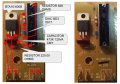
The attached pictures shows a pcb from a foot controller for a pendant style drill.I have a number of these boards which do not work and would like to try and troubleshoot the reasons.
I can understand how a chip controls the on/off to the gate on the thyristor , although I am unable to see how the gate is controlled on this pcb.
I would very much like any help in explaining how this style of AC output speed control works ,
Ps -I have not really posted much in forums before , I hope it’s all comlient etc.
Attachments
-
 159.9 KB Views: 8
 -
 302.3 KB Views: 7
")


