Pass voltage when switch turns off.

Thread Starter

sirchuck

Joined Feb 14, 2016
150
The 4.7K resistor ensures that a small current through D1 is passed to ground instead of entering into Q2's base during very dim lighting conditions.
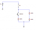
Ok, this line blows my mind. If we have a 100K ohm resistor connected to ground, and a 1k resistor connected to an LED connected to ground, you're saying the current will get used up on the 100K ohm resistor before going through the 1k resister and LED?

To me it seems a small current passed through D1 should for sure go through Q2's base because it's less resistant. I read some of the descriptions on Wikipedia on how a resistor works, but none of the explanations specify just what happens here.

To help me clarify, do the following two assumptions sound correct to you?
1) When passing 500k ohms of current through a circuit with a choice between a 100k resistor and a 1k resistor, most of the current will pass though the 1k resistor, but some of the current will be soaked up testing the resistance of the 100k resistor, although no current will pass fully through the 100k resistor while there is a less resistant path available.

2) When passing 10k ohms of current through the same circuit, the 100k resistor will soak up so much of the 10k current by testing it's resistance that not enough current will be left to pass through the 1k resistor to activate the LED load.

( We might be off topic now - but this seems like extremely good information for newbs like myself, maybe this tangent should be on it's own question thread to properly assist others.)
 
Last edited:

hobbyist

Joined Aug 10, 2008
892
The actual circuit under exam are the components (R1,R2,R3,Q1,LED1) and (the transistor part of "U1"), the led on U1 is only for simmulating purposes only, this is an opto isolator, so I'm using the function of it to simulate a light source for a photo transistor.
The variable resistor (R4) is used only for simulation purposes to bias the photo LED "U1".

Now consider the open junction between the top of R2 and the bottom of R1, this is to simulate no neg. bias to the base of Q1, thereby there is no control voltage to keep it stable under noise signals from "U1", that noise could be transistor leakage currents as well as unwanted light sources, ect...

Notice that the LED is on, and the voltage drop across R3, is around 1 volt, putting around 20mA of LED current through it, making it light bright.
Also look at the percentage value on R4 (75%) that means it has 25% more change to go before it is full negative volotage to LED (U1). This amount of input at 75% simulates noise from unwanted lighting or transistor leakage currents.
light detector non biased.jpg


Now keeping the same 75% value on R4 but now removing the results of the noisy input by hooking up R2 to the circuit to give some neg. bias, causes the effect of the noisy input to be shunted to ground, thereby keeping Q2 off until a valid input.
The voltage drop across R3 indicated now around 6mv puts around 130uA of current through the LED1.

light detector  biased.jpg


Finally consider that R4 is now brought to 80% value of resistance, this simulates a valid input signal needed for Q1 to operate properly at, so now with that amount of input signal applied to the base of Q1, causes Q1 to come out of close to being cutoff, and conduct current of around 20mA through LED1, as its suppose to do.

light detector  biased LED ON.jpg

So see neg. feedback, such as ilustrated with the 4.7K resistor is very important to keep the output clean and noise free.
 
Last edited:

hobbyist

Joined Aug 10, 2008
892
Hello Hobbyist.
If you have time would you draw the circuit you think would work? Maybe seeing it visually would help to understand your explanation. It seems like it should be possible to design a circuit that turns one LED on and another LED off during the day, then switch them at night by working with resistances instead of having to add components like more transistors or NAND gates or relays or whatever.

Hi,

Here is the circuit you were asking about,

It can be used in both modes, at the flip of a switch. (DPDT type)

(1) (daylight LED ON) & (dark LED OFF),

(2) ( daylight LED OFF) & (dark LED ON).

Now this was only designed and simulated on my computer, to do the actual build would require calculating resistor values and such. However the design concept might work, if the DPDT switch can be configured like this.

You would need a DPDT switch, shown as "J1" and "J3" on the schematic.
Also switch "J2" is only for simulation purposes only, to check the function of the circuit.
U1 would be your photo transistor.

When the switch is in the up position, you have mode (1).

when the switch is in the down position, you have mode (2).


This uses more than just a switching of resistors, as you asked about, but this is the best I could come up with, uses few more transistors but it should work, if done properly with the right component values. and the DPDT can be done like this.


light and dark detector both functions.jpg

hopes this helps with your project.
 

Attachments

Last edited:

Thread Starter

sirchuck

Joined Feb 14, 2016
150
Wow hobbiest, that looks like you did quite a bit of work. I asked mostly just for the understanding of it, but thanks for all the time you have put in to this question.
 

Thread Starter

sirchuck

Joined Feb 14, 2016
150
Hi all, I just wanted to share the finial circuit to do what I wanted. This circuit will turn on one LED during the day, then turn the other LED on during the night.

Could someone tell me if I drew the phototransistor in the right direction? The long leg goes toward negative to make it work right. An LED's long leg points to positive, so I'm a little confused if the little arrow coming out of the phototransistor is supposed to point to positive or negative on the circuit.

As promised here is the working daylight / nightlight circuit.

Phototransistor-Blink.png
 

hobbyist

Joined Aug 10, 2008
892
With no light to D1 both LED's could come on at the same time.
When D1 is activated L1 should turn off, allowing L2 when in the right direction turn on.

So its partly right in function.
It may work if R1 is low enough to shunt L2 to keep it out of conduction.
 
Last edited:

hobbyist

Joined Aug 10, 2008
892
Your on the right track:

if you would like, here is a circuit to your specs. your welcome to look over it and study the connections and the placement of the components, then you can gain a basic understanding of how you can design your circuit to work.

The opto iso, is just for simulation only.
The transistor part of it would be your photo transistor.

day,night, lite.jpg
 

Thread Starter

sirchuck

Joined Feb 14, 2016
150
Thanks for the new circuit, I'll study it some more later, it looks more robust than mine. But yes, on my circuit if you apply too much resistance, both L1 and L2 will light up.

There is nothing wrong with using R1 to shut L2 right? I mean as long as you have less resistance there than on L2, L2 should be completely off.
 

hobbyist

Joined Aug 10, 2008
892
It worked kind of fine, as long as the voltage was below 5v.
After I brought the voltage supply up to 5v. it became difficult to juggle resistor values so as to keep LED2 off with low values of R1, because too low for R1, will cause too much current through LED1. Putting a resistor in series with L2 is needed to limit current from burning it out, but too high value for that resistor was needed to keep L2 off, but when its time to turn it on the resistor was too high for it to light brightly.

A lot of trial and error to get this working with only one transistor at a voltage around 5v.
 

hobbyist

Joined Aug 10, 2008
892
Got it, it works perfect at any voltage. Within reason of 5v supply.
Transistor represents photo transistor, you could cover over one of the leds in the final assembly, the one LED is used to drop voltage so the transistor can act properly in shunting them. You may need to experiment with the resistor value to fit your supply voltage and photo transistor, ect...

I breadboarded with real components and it works real well.

day,night, lite rev.jpg
 

Attachments

Thread Starter

sirchuck

Joined Feb 14, 2016
150
It worked kind of fine, as long as the voltage was below 5v.
After I brought the voltage supply up to 5v. it became difficult to juggle resistor values so as to keep LED2 off with low values of R1, because too low for R1, will cause too much current through LED1. Putting a resistor in series with L2 is needed to limit current from burning it out, but too high value for that resistor was needed to keep L2 off, but when its time to turn it on the resistor was too high for it to light brightly.

A lot of trial and error to get this working with only one transistor at a voltage around 5v.
Ya in a circuit that needs more reliability I'd use your circuit with the transistor. I'm really only draining a 9v battery that used to be in a fire alarm before throwing it away. Right now i'm getting around 4.7 volts out of it. I am posting the finished version of the circuit below. 39K is pretty high resistance on L1 and L2, keeping the LED's a little dim but it's about the brightness I want in my line of sight.

The 4.7K is probably overkill as well, but I did test this circuit on a 5v source as well.
Phototransistor-Blink.png

One interesting thing I have found is that L2 seems to stay lit if you blink the light collected in D1 fast enough, while L1 will go on and off as expected. So yes, your transistor circuit is no doubt much more stable.
 
Last edited:

Thread Starter

sirchuck

Joined Feb 14, 2016
150
Got it, it works perfect at any voltage. Within reason of 5v supply.
Transistor represents photo transistor, you could cover over one of the leds in the final assembly, the one LED is used to drop voltage so the transistor can act properly in shunting them. You may need to experiment with the resistor value to fit your supply voltage and photo transistor, ect...

I breadboarded with real components and it works real well.

View attachment 101529
Ha cool easy circuit. :)
 

HitEmTrue

Joined Jan 25, 2016
32
Got it, it works perfect at any voltage. Within reason of 5v supply.
Transistor represents photo transistor, you could cover over one of the leds in the final assembly, the one LED is used to drop voltage so the transistor can act properly in shunting them. You may need to experiment with the resistor value to fit your supply voltage and photo transistor, ect...

I breadboarded with real components and it works real well.
Wow, so simple. Friday night I did this with two LED's, trying to have only one on at a time. There is a small range of voltage where both LED's are on. Transistor Q3 and the voltage divider at the base represent the light sensor.

lightsAndTransistors.png
 

hobbyist

Joined Aug 10, 2008
892
Transistors as switches, and a steering diode.

Now thats a robust circuit guaranteed to work all the time, because the turn off current for L2 happens at the base of a transistor, which makes it more reliable than trying to shunt current around a Led, as I showed in my last setup.

Nice design Hitemtrue.
 

Thread Starter

sirchuck

Joined Feb 14, 2016
150
Hi HitEmTrue, circuit looks good, the only question I have is why use D1 ? When Q1 is open L1 has no path to ground so it can't light, and current through R4 turns on Q2 so L2 can light up.

Whats the point of the steering diode? Does Q1 provide a ground when it's not active and D1 puts positive on the line so L1 can't light?
 

HitEmTrue

Joined Jan 25, 2016
32
Hi HitEmTrue, circuit looks good, the only question I have is why use D1 ? When Q1 is open L1 has no path to ground so it can't light, and current through R4 turns on Q2 so L2 can light up.

Whats the point of the steering diode? Does Q1 provide a ground when it's not active and D1 puts positive on the line so L1 can't light?
When current passes through Q1, L2 turns off because current does not make it to Q2...it makes a path though the diode instead. If there were simply a wire in place of the diode, L1 would never turn off, as it would always have a path to ground.
 

HitEmTrue

Joined Jan 25, 2016
32
Transistors as switches, and a steering diode.

Now thats a robust circuit guaranteed to work all the time, because the turn off current for L2 happens at the base of a transistor, which makes it more reliable than trying to shunt current around a Led, as I showed in my last setup.

Nice design Hitemtrue.
Thanks, but as mentioned, there is a range where both LED's remain lit. I don't know if it can be fixed with different resistances. Using a relay may work better.
 
Top