Part of voltage divider?

Thread Starter

WineJ

Joined Aug 23, 2015
16
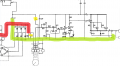
Can someone explain to me what is the purpose of R8 resistor? While R1 and R2 (in yellow) form a voltage divider to furnish voltage to the pot on the bottom, I cannot figure out, what R8 does. It is connected between the ground bus (in green) and the positive side of rectifier (in red).
It cannot be part of divider, but having it connected in parallel with a rectifier also doesn't make sense to me.
Any ideas.
The pot provide voltage for voltage controlling section, by the way.
 

Attachments

MaxHeadRoom

Joined Jul 18, 2013
28,681
I have seen it often used in circuits that don't really need it, If the DC power is disconnected at power off then it can be implemented for safety reasons, but if there is circuitry still connected to the bridge, it will often bleed off this way.
i.e. the AC power-in switched for e.g.
Max.
 

#12

Joined Nov 30, 2010
18,224
The size of the filter capacitors seems to be very important.

"Anybody that designs a product containing large storage or filter capacitors that doesn't provide "bleeder" resistor(s) to discharge the capacitors when the device is turned off is an idiot, and should be sued for gross negligence...."
 

MaxHeadRoom

Joined Jul 18, 2013
28,681
Unless the load is rather large, I would expect the capacitor value to be fairly trivial in the posted .png as it is full wave 3phase rectifier so the ripple will be 360hz and <5%.
Max.
 

Thread Starter

WineJ

Joined Aug 23, 2015
16
I have seen it often used in circuits that don't really need it, If the DC power is disconnected at power off then it can be implemented for safety reasons, but if there is circuitry still connected to the bridge, it will often bleed off this way.
i.e. the AC power-in switched for e.g.
This 3-phase rectifier gets is voltage from the secondary of a 3-phase transformer, which senses the generator output. The output of rectifier is sent to the center-tap of secondary of the current transformer, and voltage from other two taps of current transformer goes to cable-drop compensation circuitry. From there it comes to thru R1 (which I marked in yellow) to voltage adj. potentiometer on the bottom of this sketch. The output from this pot is what actually controls Q3 and thus Q1 and Q2 which provide more or less current to the exciter field.
So I guess R8 helps to decay the rectifier output when the generator being shut down? Because when the gen runs I really don't see the purpose of R8?
 

Thread Starter

WineJ

Joined Aug 23, 2015
16
Unless the load is rather large, I would expect the capacitor value to be fairly trivial in the posted .png as it is full wave 3phase rectifier so the ripple will be 360hz and <5%.
Max.
I believe both C1 and C4 are filter capacitors. C4 connected between ground bus and Point 3 (which is positive side of +28 VDC bus for transistors and IC1, IC2. + 28 comes via those two relay contacts on top right of the sketch). And C1 filters out AC component from the cable-drop section, I think.

The second post says: :It's the bleed off resistor for the main power capacitor"?
 
Last edited:
Top