Yes, I saw that circuit in the TI datasheet, but I don't have those transistors (2N2905 and TIP73), can I change those maybe for (2N2907 and TIP120) for less current?
Yes, I saw that circuit in the TI datasheet, but I don't have those transistors (2N2905 and TIP73), can I change those maybe for (2N2907 and TIP120) for less current?
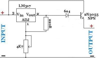
As long as your PNP and NPN loosely complement each other it will be ok and you can change them to match your requirements (Max voltage, current etc.). Just be sure to use an appropriate current limiting base resistor on the PNP or it will kill your LM317. If you choose to have multiple NPNs controlled via the one PNP (which is fine) you may want to add small value emitter resistors to them to balance the loads. The datasheet explains how the current sense resistor on the input activates the pass transistors at the required current.
EDIT also make sure they are rated for the appropriate power dissipation too.
I have read that placing voltage regulators in parallel can increase the current.
For example, a couple of 317's with max of 1A each could produce 2A. But am I right to assume that if the input voltage source can not provide the 2A, let alone the 1A, then this is not possible? Would it increase the output current at all?
Manufacturing tolerances mean that all the regulators will not output exactly the same voltage - whichever regulator puts out the highest voltage; will have to carry more than its fair share of current.
A single regulator with external bypass transistor as described in the appnotes is a better way of doing it.
As long as your PNP and NPN loosely complement each other it will be ok and you can change them to match your requirements (Max voltage, current etc.). Just be sure to use an appropriate current limiting base resistor on the PNP or it will kill your LM317. If you choose to have multiple NPNs controlled via the one PNP (which is fine) you may want to add small value emitter resistors to them to balance the loads. The datasheet explains how the current sense resistor on the input activates the pass transistors at the required current.
EDIT also make sure they are rated for the appropriate power dissipation too.
First of all in the rush I didn't noticed that the TIP73 is an NPN transistor, so it can be replaced with 2N3055 (what I have, a few new one).
I see there a few resistors (22R, 120R and 5K), I guess those can be 1/4 watts?!
But, what about that 500R resistor wattage? 5W enough? Or maybe to change that resistor for the more common 470R/5W cement resistor?
And regarding that potentiometer, to use 5K multiturn/2W or the standard linear will do it?
Hey sorry was playing some Doom there for a while.
The 22R resistor should be fine as a 1/4W as it will only develop a 0.7V drop across it, so I = V/R. 0.7V/22 = 32mA and P = V^2/R = 0.7^2/22 =
0.022W (as we have current we can check with P = V*I = 0.7*0.32 = 0.0224W, all good) .
The current flowing through your PNP base resistor depends on your maximum total current draw through all the NPNs and the voltage gain you get from the PNP and the NPNs. If we assume a gain of 20 and your maximum current is 9A (through lets say, 3 x NPNs). Each NPN is conducting 3A so its base would require 1/20th of this current so, 3/20 = 0.15A. So each NPN will need 0.15A at its base to fully turn on and supply the total 9A. Now this would mean that the PNP needs to supply 0.45A (0.15A*3) to all the NPN bases. If we again assume this PNP has a voltage gain of 20 then the current flowing from the PNP base would need to be at least 0.45/20 = 0.0225A. We already have 32mA flowing through the regulator so this additional 22mA is well within the LM317 tolerance. Now to get the base resistor for the PNP we take our desired base current and input voltage to get our resistor value. I don't know your input voltage but the resistor value will be (Vin - 0.7)/0.0225A = Base resistor value in Ohms. The power dissipation for this resistor can be determined by using the equation P = R*I^2 and then choosing one that is well over this value.
The 500R resistor is there to stop leakage current from the PNP turning on the NPNs, 1/4W should be ok here and a slightly greater or lesser value is fine.
This always helps me because I'm always forgetting
EDIT: about the potentiometer it is totally up to you what type you'd like, but definitely linear, unless the voltage drop is massive you shouldn't need too high a wattage. If you have come across this already this is a great calculator to test resistor divider configurations so you can get the best control by using the full range of the potentiometer (for example your maximum voltage may be achieved at 4K and if you use a 10K almost half the turn is essentially wasted and limits control). Also if you have a minimum voltage you don't want the output to drop below you can put a fixed small value resistor in series with the pot to get your desired range from the entire turn of the pot. Juggling the values of R1 and R2 in this calculator can help
Hey sorry was playing some Doom there for a while.
The 22R resistor should be fine as a 1/4W as it will only develop a 0.7V drop across it, so I = V/R. 0.7V/22 = 32mA and P = V^2/R = 0.7^2/22 =
0.022W (as we have current we can check with P = V*I = 0.7*0.32 = 0.0224W, all good) .
The current flowing through your PNP base resistor depends on your maximum total current draw through all the NPNs and the voltage gain you get from the PNP and the NPNs. If we assume a gain of 20 and your maximum current is 9A (through lets say, 3 x NPNs). Each NPN is conducting 3A so its base would require 1/20th of this current so, 3/20 = 0.15A. So each NPN will need 0.15A at its base to fully turn on and supply the total 9A. Now this would mean that the PNP needs to supply 0.45A (0.15A*3) to all the NPN bases. If we again assume this PNP has a voltage gain of 20 then the current flowing from the PNP base would need to be at least 0.45/20 = 0.0225A. We already have 32mA flowing through the regulator so this additional 22mA is well within the LM317 tolerance. Now to get the base resistor for the PNP we take our desired base current and input voltage to get our resistor value. I don't know your input voltage but the resistor value will be (Vin - 0.7)/0.0225A = Base resistor value in Ohms. The power dissipation for this resistor can be determined by using the equation P = R*I^2 and then choosing one that is well over this value.
The 500K resistor is there to stop leakage current from the PNP turning on the NPNs, 1/4W should be ok here and a slightly greater or lesser value is fine.
This always helps me because I'm always forgetting
EDIT: about the potentiometer it is totally up to you what type you'd like, unless the voltage drop is massive you shouldn't need too high a wattage. If you have come across this already this is a great calculator to test resistor divider configurations so you can get the best control by using the full range of the potentiometer (for example your maximum voltage may be achieved at 4K and if you use a 10K almost half the turn is essentially wasted and limits control). Also if you have a minimum voltage you don't want the output to drop below you can put a fixed small value resistor in series with the pot to get your desired range from the entire turn of the pot. Juggling the values of R1 and R2 in this calculator can help
Ahhh, the DOOM, yeah, it was one of my fav back in the days with Duke Nukem!
I just want to make some Dual Channel AVR MCU monitored Adjustable Bench Supply (0-30v), the main power source will be the ATX PSU 12V line boosted up to 31.4V (cut off by two 6A silicon diodes in series).
I wish to use only one power transistor with LM317 in my circuit.
You mentioned some 500K resistor, but there is no 500K resistor only 500 ohm, I think?!
EDIT: Or maybe just to use a single LM338K like this will same all my trouble?! What you think?
Ahhh, the DOOM, yeah, it was one of my fav back in the days with Duke Nukem!
I just want to make some Dual Channel AVR MCU monitored Adjustable Bench Supply (0-30v), the main power source will be the ATX PSU 12V line boosted up to 31.4V (cut off by two 6A silicon diodes in series).
I wish to use only one power transistor with LM317 in my circuit.
You mentioned some 500K resistor, but there is no 500K resistor only 500 ohm, I think?!
Lol Yeah 500R was what I meant . It should work ok with the ATX supply just bare in mind that as you're boosting the voltage the available current will decrease. You can also use one NPN if you'd like as long as it is rated for your maximum current, the only reason more may be used is to distribute the power dissipation over more than one component. As it's a LM317 you won't be able to go right down to 0V, I think the lowest attainable is 1.25V iirc, any lower and you risk creating a short through the regulator.
............As long as your PNP and NPN loosely complement each other it will be ok and you can change them to match your requirements (Max voltage, current etc.). .................
The don't really have to complement each other.
The PNP only carries perhaps 1/20th or less of the NPN current so it can be a much smaller, lower power device.
One thing no one ever mentions, except for the manufacturers, is that all these LM317,350 ,338 all have an Achilles heel. They can be very easily destroyed by an accidental short circuit. Who among us has not accidentally shorted the outputs or connected the power supply to a circuit with a short. Pop! I finally gave up on using these regulators because of this vulnerability.
One thing no one ever mentions, except for the manufacturers, is that all these LM317,350 ,338 all have an Achilles heel. They can be very easily destroyed by an accidental short circuit. Who among us has not accidentally shorted the outputs or connected the power supply to a circuit with a short. Pop! I finally gave up on using these regulators because of this vulnerability.
 Facebook
 Google
 GitHub
 Linkedin