 Facebook
 Google
 GitHub
 Linkedin
I'm new to the forum and truly love it, I spend time search topics relating to parallel port but didn't find what I'm looking for.
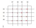
I'm creating something similar to the functionality of a matrix keypad, and I have attached an illustration (note that I have 10 outputs and 6 inputs, but I attached a simplified diagram).
B7-B4 are considered outputs so I would write '0' or '1' to them, and then the data are read through B3-B0 (inputs). I have wrote a program in VC++ to control the parallel port pins and everything seems to work fine. My problems lays in the interface circuit.
As the idea of the keypad, I want to toggle an output to low one output at a time. After I toggle an output to low, I want to scan all inputs and find a zero bit as well. The program simply returns the interaction node # shown on the keypad.
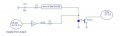
The parallel port outputs (I'm using D6-D0 from the data pins and C3-C1 from the control pins) are buffered by a line drive SN74ABT827 , and through a resistor sending a '1' or '0' to the keypad. The keypad inputs are opto-coupled to isolate the keypad from the parallel port using PC3Q710. I have a schematic attached.
The purpose here is to receive the node # where both input and output are toggled low '0', so in order to do that I figured there are 4 cases I have to take into account:
1) If the Output is high '1' and the input is read '1': '1' would be received, hence Vf across the opto-coupler is about 1.2 typically, I measured to be about 1.03V. What's the minimum If current that triggers the LED in the opto-coupler, the data sheet mentions If max to be 10 mA?
2) If the output is low '0' and the input is read '1': again '1' would be read , but the voltage condition changes.
3) If the output is high '1' and the input '0': I would like '1' to be received.
4) If the output is low '0' and the input '0': That's the only case where I want to receive a '0' to indicate there is a contact between an input row and an output column.
I'm quite confused about these conditions, and don't know how to exactly choose the resistor values to satisfy the conditions.
If this sounds confusing from someone, I will explain it from the matrix keypad prespective. Let's say someone pressed on the keypad # 1 (check the attachment). B3-B0 are initially pulled up, but once a pressing has been made, B3 should read '0' only once B7 is '0'. B7-B4 would be triggered to low one at time and then scanned the input to find the zero bit.
What are the constraints I have to take into account to choose the right resistor values? Any suggestions on the circuits if I'm doing anything wrong, please let me know.
I know some people might be keen to using Micro controllers on the matrix keypad, but I have to use VC++/VB in my application. Any input would be helpful, thanks.
I'm creating something similar to the functionality of a matrix keypad, and I have attached an illustration (note that I have 10 outputs and 6 inputs, but I attached a simplified diagram).
B7-B4 are considered outputs so I would write '0' or '1' to them, and then the data are read through B3-B0 (inputs). I have wrote a program in VC++ to control the parallel port pins and everything seems to work fine. My problems lays in the interface circuit.
As the idea of the keypad, I want to toggle an output to low one output at a time. After I toggle an output to low, I want to scan all inputs and find a zero bit as well. The program simply returns the interaction node # shown on the keypad.
The parallel port outputs (I'm using D6-D0 from the data pins and C3-C1 from the control pins) are buffered by a line drive SN74ABT827 , and through a resistor sending a '1' or '0' to the keypad. The keypad inputs are opto-coupled to isolate the keypad from the parallel port using PC3Q710. I have a schematic attached.
The purpose here is to receive the node # where both input and output are toggled low '0', so in order to do that I figured there are 4 cases I have to take into account:
1) If the Output is high '1' and the input is read '1': '1' would be received, hence Vf across the opto-coupler is about 1.2 typically, I measured to be about 1.03V. What's the minimum If current that triggers the LED in the opto-coupler, the data sheet mentions If max to be 10 mA?
2) If the output is low '0' and the input is read '1': again '1' would be read , but the voltage condition changes.
3) If the output is high '1' and the input '0': I would like '1' to be received.
4) If the output is low '0' and the input '0': That's the only case where I want to receive a '0' to indicate there is a contact between an input row and an output column.
I'm quite confused about these conditions, and don't know how to exactly choose the resistor values to satisfy the conditions.
If this sounds confusing from someone, I will explain it from the matrix keypad prespective. Let's say someone pressed on the keypad # 1 (check the attachment). B3-B0 are initially pulled up, but once a pressing has been made, B3 should read '0' only once B7 is '0'. B7-B4 would be triggered to low one at time and then scanned the input to find the zero bit.
What are the constraints I have to take into account to choose the right resistor values? Any suggestions on the circuits if I'm doing anything wrong, please let me know.
I know some people might be keen to using Micro controllers on the matrix keypad, but I have to use VC++/VB in my application. Any input would be helpful, thanks.
Attachments
-
 11.2 KB Views: 105
 -
 15.4 KB Views: 122


