Parallel charging a large array of high capacity prismatic LiFePO4 cells

Thread Starter

OneMist8k

Joined Aug 4, 2020
12
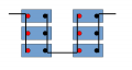
You should do it like the lower diagram, keeping the wires as far as possible the same length.
That makes sense. I am no longer going to try to charge all 48 at once. The idea was to get them to charge and balance all at the same time and I've learned that isn't practical. Fewer will be charged at a time in parallel, maybe just two, using the star method you've illustrated. After they will be paralleled together to top balance before assembling in the pack.
An alternative to pigtails is nickel-plated copper busbar. I don't recommend these for prismatic cells as its hard to keep the cell fixed with all the vibration and shock and I've had cells break internally. They are great for the cylindrical cells in the orange holders. Also the ones supplied by the cell vendors are something like 0.75mm thick and have less square mm of copper than 10 or 8AWG so you have to stack them which leads to other issues.
The vendor sent busbars with the cells, but they are terrible and nowhere near the rated ampacity I need. I ended up buying 1" wide x 1.4" thick copper bars (I think coated with tin) and made my own by cutting and drilling. The bunk was built with sturdy "L" brackets so the cells will all at the same level. This is going on a sailboat where vibration shouldn't be a problem. But I will be watching for breakage.
For your 16S3P arrangement...

So I gotta ask if I'm using the right terminology. Is it 16S3P or 3P16S? This is a single battery pack delivering 48 volts nominal, not 16 prismatics in series paralleled with three others. In other words, each battery "cell" is going to be 3 prismatic bricks in parallel, and 16 of those "cells" will be in series. "Cell" is intentionally in quotes to distinctively represent 3 paralleled bricks.
 

du00000001

Joined Nov 10, 2020
191
Nomenclature is usually xSyP.
Not sure whether some standard exists to express paralleling cell strings because this would require multiple cell balancing. So the usual approach is to have as-many-as-required cells in parallel, these parallel blocks serialized then.
 
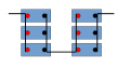
For your 16S3P arrangement you must connect all cells in one group to all the cells in the adjacent group... its tempting and easy to connect like the top diagram, but that's wrong. You should do it like the lower diagram, keeping the wires as far as possible the same length.
View attachment 273684

Here's why...

If you connect cells in a group together but only have a single connection group to group from the middle cell then the currents are unbalanced and the middle cell will discharge faster than the outer ones.

View attachment 273683

By using a star connection the load is shared equally across cells. This also benefits charging too. Your balance wire should be connected to the star point.

View attachment 273689


An alternative to pigtails is nickel-plated copper busbar. I don't recommend these for prismatic cells as its hard to keep the cell fixed with all the vibration and shock and I've had cells break internally. They are great for the cylindrical cells in the orange holders. Also the ones supplied by the cell vendors are something like 0.75mm thick and have less square mm of copper than 10 or 8AWG so you have to stack them which leads to other issues.
How about this configuration:
1660328906057.png
 

Attachments

Irving

Joined Jan 30, 2016
5,191
16S3P means 16 series of 3 paralleled.

What do you plan to charge them with? There are very few good chargers out there. Either they can't handle the required charge current or they don't balance accurately enough.

How about this configuration:
Draw the equivalent circuit and you tell me... :)
 

Thread Starter

OneMist8k

Joined Aug 4, 2020
12
Draw the equivalent circuit and you tell me... :)
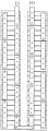
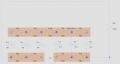
So this is the 16S3P configuration. It has to be this shape, btw, because of limitations where this will fit. Long and narrow.

CellConfig.jpg


You asked what is charging it. When it is installed, there is a 48v 25A charger for the above configuration. The BMS will have taps to each "cell" of three prismatics. I know the BMS will not give me information on each individual prismatic, only down to the 3 parallel "cell". Not perfect, but I've accept that.
 

Irving

Joined Jan 30, 2016
5,191
So this is the 16S3P configuration. It has to be this shape, btw, because of limitations where this will fit. Long and narrow.
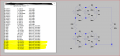
Assuming your busbars are near pure copper 25.4mm (1") wide, 6.3mm (1/4") thick and ignoring the plating then they are roughly 2μΩ per cm. Allowing 5cm between cells, each inter-cell resistor is approx 10μΩ.

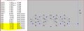
The equivalent circuit for the first 2 packs is below. At 100A the difference between cells is only 0.25A. That will easily be hidden by cell internal resistance variations (for the simulation all cells have 1mΩ IR). I'd say that's fine! Yes there is stilla big variation in current between R1 and R2 but these busbars can take it.

1660336168764.png
 
Last edited:
Baaad,very bad... Not only the cell currents are unbalanced, but look at the difference between connections R1 and R2, R2 carries twice the current of R1!

View attachment 273712
That simulation was an eye opener for me.
I was scratching my head trying to figure out why it was so bad.
Then I realized how all of the nodes interacted.
The configuration will work for 2 in parallel but not more.
It's interesting because in the off grid solar industry it's been recommended for years but I can see now that your first recommendation with equal length interconnects with a single common point is far better.
This comes at the perfect time because I've had a 2P8S setup for years and I am upgrading to a 4P8S setup shortly and was going to use the same setup.
Learn something new every day! Thank you.
 

Irving

Joined Jan 30, 2016
5,191
That simulation was an eye opener for me.
I was scratching my head trying to figure out why it was so bad.
Then I realized how all of the nodes interacted.
The configuration will work for 2 in parallel but not more.
It's interesting because in the off grid solar industry it's been recommended for years but I can see now that your first recommendation with equal length interconnects with a single common point is far better.
This comes at the perfect time because I've had a 2P8S setup for years and I am upgrading to a 4P8S setup shortly and was going to use the same setup.
Learn something new every day! Thank you.
You're welcome. Of course, as i showed later, if you have massive low impedance busbars, where the inter-cell resistance << cell internal resistance, these layouts are workable. So they 'work' for lead-acid at the 12v battery level, but if you want Max performance and longevity for high-density LiPo and LiFe cells you need to be cleverer. IMHO and, as always, YMMV!
 

Thread Starter

OneMist8k

Joined Aug 4, 2020
12
You're welcome. Of course, as i showed later, if you have massive low impedance busbars, where the inter-cell resistance << cell internal resistance, these layouts are workable.
Since it's already well established that I'm an idiot, I can ask this next question without fear of being judged. The manufacturer's specifications on the cells say the internal resistance of these prismatic cells are less than .4 milliohms. That is .0004 ohms, correct? I'm wondering if I should measure the internal resistance of each cell from time to time. Googling now how to do that.

I may be straining your generosity in sharing knowledge here, but I'm not an electrician so I'm having a hard time understanding the illustrated diagram... I've been going right to your explanation. Not only would I like to understand the diagram and results, but I'm very curious about the simulation software. Is this PC based at a reasonable price?
 

Irving

Joined Jan 30, 2016
5,191
I may be straining your generosity in sharing knowledge here
Not at all, that's what the AAC community is all about...

Since it's already well established that I'm an idiot, I can ask this next question without fear of being judged. The manufacturer's specifications on the cells say the internal resistance of these prismatic cells are less than .4 milliohms. That is .0004 ohms, correct? I'm wondering if I should measure the internal resistance of each cell from time to time. Googling now how to do that.
A good LiFePO4 cell will be under 1mΩ, or < 0.001Ω. 0.4mΩ or 0.0004Ω is good. Measuring internal resistance isn't complicated but there are different methods. Normally the manufacturer specifies the test method they used; basically you measure the open circuit voltage, then measure the terminal voltage when loaded at a known current, typically 1A and you do this repeatedly at 1kHz. At 1A thats a voltage difference of 1mV, so accurate and fast-reacting instrumentation is ideally needed.

I may be straining your generosity in sharing knowledge here, but I'm not an electrician so I'm having a hard time understanding the illustrated diagram... I've been going right to your explanation. Not only would I like to understand the diagram and results, but I'm very curious about the simulation software. Is this PC based at a reasonable price?
Software is free from Analog Devices.

All conductors have a fixed electrical resistivity per cubic meter, and therefore, given the cross-sectional area, you can calculate the resistance per cm of buss-bar. So between each connection point you can treat the buss-bar as a fixed resistor. Maybe this diagram overlaying physical buss-bar and electrical schematic will help.

1660406310916.png
 

jrb_sland

Joined Dec 24, 2021
25
May I suggest that you study the following elderly post by the late Jack Rickard? He was an early adopter of everything to do with EVs, and in particular did some good work studying LiFePO4 cells & their properties. He became a staunch advocate of bottom-balancing, and was of the opinion that many off-the-shelf top-balancing circuit boards were dangerously flawed. It was his experience that once a set of cells was bottom balanced, at say 2.500 volts, then series-connected as a battery, that there was no "drift" observable during normal use, therefore a balancing arrangement was entirely unnecessary. Of course it is essential that no parasitic loads on the cells exist - even tiny differences in the cell loading by, for instance, a BMS {battery management system} will CAUSE a loss of balance. The website below contains all of Mr. Rickard's posts, some of which include access to his YouTube videos, so I suggest you read around to get a feel for the subjects under discussion. Remember that your lithium cells are little powerhouses, and can be dangerous in the extreme if you misuse them.

https://www.evtv.me/2013/07/19/the-thrill-of-victory-and-the-agony-of-the-feet/

You need to ask, and find your own answers, to the following questions. Beware, my answers might be flawed...

1} Why do batteries need balancing?
A: there is some evidence that cells may drift with time, so we should have balancing arrangements. This certainly happens with lead-acid batteries, but is not necessarily true of other chemistries. Where is the evidence?
2} What is the problem with out-of-balance cells?
A: in a long series string of cells, if one cell has less energy than the others, it's terminal voltage will crash through zero, & even go negative, as the battery approaches a state of full discharge. Similarly, a weak cell charged in series with good cells might overcharge & be injured. Neither situation is good for lithium cells of any subtype. But bottom-balanced cells will all go flat at the same time, so no harm done. A discharged cell cannot deliver large currents which would cause reversed polarity.
3} Top balance or bottom balance?
A: Mr. Rickard, & others, found that top-balanced battery packs exhibited a lot of "churn", i.e. individual cell voltages bouncing around when they approached full charge. What, then, do you mean by "balanced"? Bottom balancing, while time-consuming to do correctly, is done only once. You might want to use a hand-held voltmeter from time to time to verify the cell balances {at a low state-of-charge} as a sanity check, but it shouldn't be a requirement. Once per year might suffice? Reminder - my comments here only apply to LiFePO4 cells!!

Hope this helps. There is a significant amount of confusion about various battery types & their optimum care & feeding. Good luck with your sailboat project!
 

Thread Starter

OneMist8k

Joined Aug 4, 2020
12
May I suggest that you study the following elderly post by the late Jack Rickard?
I started reading the post. It is quite lengthy; I haven't finished it yet but I get his thesis. But gosh, the blog post is almost ten years old! Haven't his theories and postulations been verified, refuted, or refined by now?

He became a staunch advocate of bottom-balancing, and was of the opinion that many off-the-shelf top-balancing circuit boards were dangerously flawed. It was his experience that once a set of cells was bottom balanced, at say 2.500 volts, then series-connected as a battery, that there was no "drift" observable during normal use, therefore a balancing arrangement was entirely unnecessary.
Fascinating. My plan was always to stay between the knees in charging, but needed to choose between a top and bottom balance. I was choosing a top balance because I didn't want to run the risk of a cell overcharge even when charging only to 3.6 volts.

1} Why do batteries need balancing?
A: there is some evidence that cells may drift with time, so we should have balancing arrangements. This certainly happens with lead-acid batteries, but is not necessarily true of other chemistries. Where is the evidence?
I have seen my near-fully discharged cells (2.7 - 2.8 volts) drift after becoming balanced here at the bottom. However, perhaps they do not drift when being used (charged and discharged), is that what you are saying?

2} What is the problem with out-of-balance cells?
A: in a long series string of cells, if one cell has less energy than the others, it's terminal voltage will crash through zero, & even go negative, as the battery approaches a state of full discharge. Similarly, a weak cell charged in series with good cells might overcharge & be injured. Neither situation is good for lithium cells of any subtype. But bottom-balanced cells will all go flat at the same time, so no harm done. A discharged cell cannot deliver large currents which would cause reversed polarity.
What is defined as a "state of full discharge"? Two volts? Zero volts?

3} Top balance or bottom balance?
A: Mr. Rickard, & others, found that top-balanced battery packs exhibited a lot of "churn", i.e. individual cell voltages bouncing around when they approached full charge.
Maybe I should read the post, but is this "churn" he is talking about during balancing? Is there a BMS in the loop? From what I understand of BMS balancing logic, I can see where this churn is coming from.

Bottom balancing, while time-consuming to do correctly, is done only once.
Why would this be any different than top balancing? When the battery is charged, the BMS will still try to keep them in balance regardless if they started out top or bottom balanced, no?

Hope this helps. There is a significant amount of confusion about various battery types & their optimum care & feeding. Good luck with your sailboat project!
Thanks! I am particularly keen on the "
 

Irving

Joined Jan 30, 2016
5,191
One of the biggest problems with BMS balancers is churn at the top-end because the non-integrated BMS has no control of the charging current. If you passively need to bypass a cell but your charger source is still delivering a high current then all you can do is switch off the charging source until the bypassed cell voltage drops into the 'window' again, then reapply the charge current - if that is greater than the bypass current the bypassed cell will again trip off the charge. A good 'N' cell charger with integrated top-balancing will dial the current back until all cells are holding to 3.6v ± 5mV and charge current < 0.01C.

Personally, for a wheelchair, I never fit a BMS. The last thing I need is some over-zealous voltage monitor cutting off the battery if one cell under heavy load (>150A) drops a few mV under 2.9V (my max discharge voltage for longevity) as I'm crossing a busy road and hit 'wheelie mode' to avoid a red-light jumper (yes its happened a few times, if I was still using SLA I'd probably be dead by now). I have a multi-cell voltage monitor of my own design that bluetooth's cell volts (and SoC by 'columb counting') to an app on my phone and notifies me when one or more cells are reaching my terminal voltage. I then decide when I need to recharge. I use a Revolectrix PL8 8S charger @ 40A that top balances at 3.595v; balancing current is 3A+ and typically takes 15 - 20min after a recharge from 10% SoC, less if I charge earlier. I'm currently working on an on-board 1kW individual cell-level 30A charger that removes the need for balancing completely.
 

Irving

Joined Jan 30, 2016
5,191
Addendum to the pre-charging routine. Charge all cells as you see fit but finalize individually. Measure O/C voltage after 1h off charge - should be stable by then - and record on cell (painters tape and a Sharpie). Put all cells aside in a stable environment for as a long as possible, at least a week but preferably a month. Use an accurate cell monitor to measure cell volts to determine self-discharge and after, internal resistance. Group into 3-s best matched on self-discharge voltage and IR. This will give the best pack for balancing, top or bottom, with least differential stress on cells.
 

jrb_sland

Joined Dec 24, 2021
25
" I started reading ..." Welcome to reality - I have no idea whether Rickard's ideas have been superseded by more modern approaches, but I thought you might be interested to read some of the historical information. My concern is that some portion of the advice available to us may be flawed.

" Fascinating. My plan ..." Yes, overcharge can be an issue, but that is the whole point of cell balancing in the first place. Note that with bottom balancing there is no reason to expect exact cell voltage matching at full charge, only at "flat battery" state, so you need to observe individual cell voltages after/during the first few charge cycles to determine your most appropriate charge cutoff voltage as measured end-to-end of the battery. 48 cells * 3.6 volts/cell = 172.8 volts. Say you have one "weak" cell that hits 3.6 volts a few minutes before the others - should your final cutoff then be at say 171.5 volts? How much extra run time would you get by ignoring the over-charging celI? I don't know the answer... Ideally you have a small surplus of cells & can afford the time to carefully sort them to get best matches. "Irving" has excellent advice - take your time, measure carefully, make good notes, label the cells.

" I have seen ..." That depends on how long you wait with the cells open-circuit {charger disconnected} before measuring their terminal voltage. My {fuzzy} recollection is that Jack waited several hours, or even overnight, before coming to a conclusion re stable state-of-charge. I'd also guess that cell temperature matters. I can only recommend you do the experiments & learn these things by your own experience with the cells you have at hand.

" What is defined ..." Anything below about 2.5 volts {for LiFePO4 cells} is fully discharged in practice. The terminal voltage of the cell crashes to zero very quickly after it falls below 2.5 under load...

" Maybe I should ..." Yes, Jack is talking about 2013-vintage top-balancing BMS systems exhibiting chaotic cell voltages as they approach full charge. The whole point of a bottom-balanced battery is that you DO NOT USE a BMS! The cells have been balanced at a low state-of-charge {specifically to prevent reverse-polarity on a weak cell}, & you are expecting them to NOT drift away from that condition as the months go by.

" Why would this ..." See above. As "Irving" correctly points out, a BMS may cause more problems than it solves.

OK. I've said my piece & rest my case. Study the comments made by "Irving" & myself with careful attention to the subtIe details. I hope you get your sailboat running safely. Sounds like fun! These new batteries are fascinating & powerful tech, but require a certain amount of expertise to use. All the best!
 

Irving

Joined Jan 30, 2016
5,191
Further thoughts on BMS.. What is it's main purpose? To stop idiots overdischarging or overcharging the cells. Secondary purpose, limit discharge current. Your 150Ah cells 3P will easily handle a 1500A discharge for 5 - 10sec so overcurrent limiting isn't really an issue. If you're worried about protecting the wiring against short circuits put a 250A slow-blow fuse or a 500A thermal trip in circuit. As to overcharging or overdischarging - it's entirely under your control: accurate voltage monitoring and a proper charging regime with a decent charger is all that's needed, no BMS required.
 

Thread Starter

OneMist8k

Joined Aug 4, 2020
12
Further thoughts on BMS.. What is it's main purpose? To stop idiots overdischarging or overcharging the cells. Secondary purpose, limit discharge current. Your 150Ah cells 3P will easily handle a 1500A discharge for 5 - 10sec so overcurrent limiting isn't really an issue. If you're worried about protecting the wiring against short circuits put a 250A slow-blow fuse or a 500A thermal trip in circuit. As to overcharging or overdischarging - it's entirely under your control: accurate voltage monitoring and a proper charging regime with a decent charger is all that's needed, no BMS required.
I bought my BMS, an Orion Jr., a while back. It is still sitting in the box waiting.

In the meantime, I bought a Thornwave smart shunt a few days ago. This little guy has high and low voltage cutoff signals, keeps up to 3 years of monitoring history in it's own memory, and a Bluetooth interface to it's own free app that has amazing data. I'm thinking this does almost everything the Orion Jr. does at half the cost. Almost. The Thornwave can only give information on the whole pack while the Orion Jr has info down to the cell level because of the cell taps, but that info is compromised a bit when a "cell" is actually 3 prismatics in parallel (3P).

Also in the meantime, I've read more than one article and seen videos saying a BMS really isn't needed when bottom balancing. When I started this project I thought it was imperative to have one. I'm starting to see why.

While all this has been happening I've started charging some of the cells with my bench top power supply. Cells have been charged 2P at a time (remember, I discovered charging all 48P at once was impractical, so I pivoted to charging two at a time). Charging each cell to 3.6 volts (actually a bit less after they disconnect from the charger for a bit), I've discovered that I can't top balance them in parallel the same way as I did when they were discharged. Connecting 4 or 6 in parallel and letting them sit for a couple of days does not bring them in line. There is always some difference between cells. Fully discharged they balance to +/- .001 volts, but not at the top.

This has me re-thinking not only my approach to balancing, but how the configured bank will ultimately be used. Testing these cells on the bench in the shop and seeing their behavior has been eye-opening.
 

du00000001

Joined Nov 10, 2020
191
Further thoughts on BMS.. What is it's main purpose? To stop idiots overdischarging or overcharging the cells. Secondary purpose, limit discharge current. Your 150Ah cells 3P will easily handle a 1500A discharge for 5 - 10sec so overcurrent limiting isn't really an issue. If you're worried about protecting the wiring against short circuits put a 250A slow-blow fuse or a 500A thermal trip in circuit. As to overcharging or overdischarging - it's entirely under your control: accurate voltage monitoring and a proper charging regime with a decent charger is all that's needed, no BMS required.
The main purpose of the BMS is to prevent overcharging the "weaker" cells. As a side effect you get the individual cell voltages, so if's easy to detect individual cells reaching the "empty" state.

A bit more about bottom balancing:
  • Once bottom balancing is finished, all cells - irrespective of their capacity - show the same cell voltage.
  • When charging such a string, it cannot take more charge than the one fitting into the weakest cell. (The stronger cells will show a lower SOC, but still hold the same charge.)
  • If you know the end-of-charge string voltage (sum of all voltages of individual cell (blocks) connected in series), there is no urgent need for monitoring the individual cell voltages as long as the cells age uniformly (capacity loss in % of start capacity).

While measuring individual cell voltages per BMS, charge balancing doesn't make much sense:
  • During charging, you may get more charge into the string if the weakest cell is bypassed.
  • BUT THIS DOESN'T HELP as during discharge you cannot "harvest" more than the charge stored in the weakest cell !
  • So while all cells are at max. SOC when a BMS is involved, the charge that can be extracted is the same as for bottom balancing. But the cells are stressed more mechanically towards max. SOC, which may affect cell life.

So what's my resume?
  • While bottom balancing may not be workable for series production, it seems to be the better approach. It may or may not eliminate some individual cell voltage supervision, but it certainly eliminates the need for charge balancing (at least for quite some time).
  • Top balancing may be comfortable for the battery OEMs (as the production effort is reduced), but it may waste energy during each and every charging cycle and in the end doesn't "press" more energy into a given battery. PLUS: a balancing-capable BMS adds quite some cost.
 
Top