Paper Shredder — Unable to Power On Normally

Thread Starter

Kisayax

Joined Oct 29, 2025
10
Hello everyone,


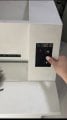
I’ve recently encountered some difficulties while repairing a paper shredder. When I press the “Start” button on the membrane switch, the digital display is supposed to stay on constantly, but now it lights up briefly and then goes off.


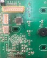
Figure 1 shows the control board:


  • The position marked with a red box is connected to the membrane switch, which has three buttons in total.
  • The blue box marks the connection to the paper sensor.
  • The yellow box shows the area connected to the power board.

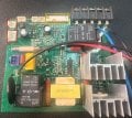
Figure 2 is the power board:


  • The red and blue wires at the top right are connected to a start capacitor.
  • All five pins are connected to the motor of the cutting blades.
  • The blue box marks the limit switch for the waste bin door.
  • The red box marks the input and output of the transformer.
  • The yellow box marks the connection to the control board.

I have already performed the following troubleshooting steps:


  1. Removed and checked each capacitor — no visible damage or open circuit found.
  2. Checked the power supply from the power board to the control board — the 4.94V operating voltage remains stable when the button is pressed.
  3. Verified that both the paper sensor and the waste bin door limit switch are functioning correctly.
  4. Disconnected the load, but the same error still occurs.
  5. The device has an overcurrent reset function that requires holding down the “Reverse” button while powering on, but due to this issue, the “Reverse” button still causes the display to turn off.

I’m wondering whether this fault might be related to the microcontroller’s reset or zero-cross detection pin, but I’m not sure where to start. Any help or advice would be greatly appreciated.
 

Attachments

wayneh

Joined Sep 9, 2010
18,096
When I press the “Start” button on the membrane switch, the digital display is supposed to stay on constantly, but now it lights up briefly and then goes off.
I've fixed more than one appliance by bypassing membrane switches with regular old pushbutton switches. Membrane switches simply aren't all that reliable.

Just my 2¢
 

Thread Starter

Kisayax

Joined Oct 29, 2025
10
I've fixed more than one appliance by bypassing membrane switches with regular old pushbutton switches. Membrane switches simply aren't all that reliable.

Just my 2¢
I tested the membrane switch pins with a multimeter, and each press gives a precise response. Also tried using jump wires to connect an external foot switch,but this fault persists.
 

Rockettfuel

Joined Sep 17, 2025
29
My first assumption is that it goes into overcurrent protection mode.
Have you tried testing C7, C8, C9 in Ohms mode on your DMM?
Black probe on ground and Red probe testing both sides of the capacitor.
Forgive me if you know this already I only want to confirm.

Also you can check for shorts by using a thermal camera on the power
board to detect hotspots when injecting voltage from a power supply.
 

du00000001

Joined Nov 10, 2020
189
There seem to be signs of overheating on the yellow-boxed connectors (1 pin) - weird

Maybe you should monitor the 5 V supply with a scope - a weak power supply (still delivering some voltage, but no current/power) might show such effects: the voltage is sufficient until the LED is lit. And/or try loading the 5 V statically with e.g. 270 Ohms and check the voltage then!
 

Thread Starter

Kisayax

Joined Oct 29, 2025
10
My first assumption is that it goes into overcurrent protection mode.
Have you tried testing C7, C8, C9 in Ohms mode on your DMM?
Black probe on ground and Red probe testing both sides of the capacitor.
Forgive me if you know this already I only want to confirm.

Also you can check for shorts by using a thermal camera on the power
board to detect hotspots when injecting voltage from a power supply.
I tested those three capacitors, and they can charge normally. Recently, I got a thermal imager, and when I power the device on, the NTC resistor in the purple box on the power board goes up to about 50 °C. The voltage regulator chip in the orange box is around 30 °C, and nothing else seems to be heating up noticeably.
 

Thread Starter

Kisayax

Joined Oct 29, 2025
10
There seem to be signs of overheating on the yellow-boxed connectors (1 pin) - weird

Maybe you should monitor the 5 V supply with a scope - a weak power supply (still delivering some voltage, but no current/power) might show such effects: the voltage is sufficient until the LED is lit. And/or try loading the 5 V statically with e.g. 270 Ohms and check the voltage then!
I’m assuming you’re referring to the brown residue. That is actually adhesive originally applied by the manufacturer for component fixation. I haven’t performed a load testing yet, but at the very least, when I press the button, the 5 V shows no noticeable voltage fluctuation.
 

Thread Starter

Kisayax

Joined Oct 29, 2025
10
Will the motor run when it's powered externally? The most common paper shredder problem is jammed shredding mechanism.
After paper is detected and the membrane switch is pressed, held, and released, the motor and cutter operate for 1-2 seconds and shred little portion of the paper, but stop prematurely. However, repeating the entire process several times eventually results in the entire paper being shredded. So the cutter and motor probably aren't jammed.
 

Rockettfuel

Joined Sep 17, 2025
29
Oh this issue is interesting.
I would start on the section of the power board that is
responsible for sending low voltage to the control board.
It may have a possible short.

Make sure the control board is disconnect from the power board.
To confirm I attached an image of the section power board and
would start from the bottom the low voltage section and work up
toward the control board connector.
For U5 it looks like the low voltage regulator, test the output pin and
common ground in Ohmns, anything close to 0Ω you know is a short.
Test the capacitors and resistors in Ohmns to see if you
get anything close to .
Hmm C7, C6, C5 look unusally dark in the photo.
Also test the resistance of those small mosfets Q7, Q6, Q5.

If no faults are found then I would connect the power board to
a power supply and measure the voltage of the control board connector
VCC pin. Which I think is the first pin from the right but you would have to
verify which is the correct pin. See if that pin provides a steady voltage.

If VCC pin voltage is steady then measure U5 voltage black probe on ground pin
and red on output pin (3.3V or 5V) and then input pin (6V-20V).

If no faults on the power board then the fault is most likley on the control board. Screenshot 2025-11-19 at 4.56.31 PM.png
 

KeithWalker

Joined Jul 10, 2017
3,604
After paper is detected and the membrane switch is pressed, held, and released, the motor and cutter operate for 1-2 seconds and shred little portion of the paper, but stop prematurely. However, repeating the entire process several times eventually results in the entire paper being shredded. So the cutter and motor probably aren't jammed.
That would indicate to me that the motor is drawing too much current. Everything else appears to be working correctly. I recommend that you double check the motor and cutting assembly.
 

Thread Starter

Kisayax

Joined Oct 29, 2025
10
Oh this issue is interesting.
I would start on the section of the power board that is
responsible for sending low voltage to the control board.
It may have a possible short.

Make sure the control board is disconnect from the power board.
To confirm I attached an image of the section power board and
would start from the bottom the low voltage section and work up
toward the control board connector.
For U5 it looks like the low voltage regulator, test the output pin and
common ground in Ohmns, anything close to 0Ω you know is a short.
Test the capacitors and resistors in Ohmns to see if you
get anything close to .
Hmm C7, C6, C5 look unusally dark in the photo.
Also test the resistance of those small mosfets Q7, Q6, Q5.

If no faults are found then I would connect the power board to
a power supply and measure the voltage of the control board connector
VCC pin. Which I think is the first pin from the right but you would have to
verify which is the correct pin. See if that pin provides a steady voltage.

If VCC pin voltage is steady then measure U5 voltage black probe on ground pin
and red on output pin (3.3V or 5V) and then input pin (6V-20V).

If no faults on the power board then the fault is most likley on the control board. View attachment 359117
U5 is actually an optocoupler with the model PC817. I removed it from the board and tested it separately. When voltage is applied to one side, the other side can conduct normally.


U4 is the voltage regulator used on this power board, model 78M05. I marked it in the attached image with a fluorescent pen. According to thermal imaging inspection, there is no abnormal hotspot, and I estimate its operating temperature to be around 40–50 °C.


Capacitors C7, C6, and C5 were measured with an LCR meter and showed no issues. The resistance measurements of MOSFETs Q7, Q6, and Q5 also appear normal.


The 5 V supply to the control board is normal as well.

regulator.png
 

Thread Starter

Kisayax

Joined Oct 29, 2025
10
That would indicate to me that the motor is drawing too much current. Everything else appears to be working correctly. I recommend that you double check the motor and cutting assembly.
I have attached another image. Inside the marked area, there are five wires connected to the motor: red, red, black, brown, and blue.


The two red wires are the signal lines of the temperature sensor. If I disconnect them, the digital display shows a thermometer icon.


The remaining three wires are connected to the motor windings. The black and blue wires are in parallel with a start capacitor (model CBB60), so I believe the brown wire should be the common terminal.


After disconnecting these three load wires, the display still shows the same flashing behavior when I press the switch. I then connected a light bulb to replace the load, but the bulb did not light up at all. After pressing the switch, the bulb did not even flash.
motor lines.png
 

Thread Starter

Kisayax

Joined Oct 29, 2025
10
Thanks everyone for the help. After some trial and error on my side, I found that if I reverse the wiring of the start capacitor, the device can actually start up normally. The red power indicator stays on steadily, and when I feed in paper, I can clearly hear the relay clicking, but the motor shows no sign of running.


After I reconnected the start capacitor wiring back to its original configuration, the device was still able to start normally. This time, I measured the voltage on the motor wires (with the three load wires disconnected). After the relay is energized, I can measure 220 V between black and brown, and also between brown and blue. However, once the three load wires are connected, the voltage disappears.


During this process, I replaced two triacs with new ones, but the fault remained. I also removed both relays and tested them separately; when 12 V is applied to one side, they energize normally.

motor lines.png
 

Rockettfuel

Joined Sep 17, 2025
29
I think its awesome that you haven't given up on troubleshooting this shredder and I've
definitely been looking forward to your updates.
Now based on your last update I'm thinking that the issue could be the motor or gear assembly.

Can the motor spin freely by hand and do the gears turn smoothly?
Have you removed the motor and visually inspected it? Especially the coils? Its possible at some
point the motor may have overheated and now short under load. Have you removed the gears and
inspected the teeth? Can you do a continuity and resistance test on the motor? Or try injecting
power into the motor in isolation? I'm assuming its a universal motor.
 
Top