P-Channel MOSFET Vgs

Thread Starter

jwilk13

Joined Jun 15, 2011
228
I posted a similar thread here, but the result we came to there is slightly different than what I have now.

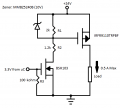
I have a microcontroller switching ON and OFF 3.3V at a very low frequency (once per second maybe). I have a 24V supply now, and the main difference between the circuit here and the one I finally ended up with in my previous post is that this one uses a resistor divider network and zener diode to keep Vgs at 10V. Is this the right way of doing it? Any help would be appreciated.
 

Attachments

crutschow

Joined Mar 14, 2008
38,935
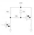
For low speeds you can eliminate the zener by putting the two resistors in series to the drain of the first transistor. Connect the junction of the resistors to the gate of the second transistor. That will limit the maximum Vgs on the second transistor to 12V.
 

Thread Starter

jwilk13

Joined Jun 15, 2011
228
At that low switching speed, either circuit would work.
I'm pretty sure I understand why it would work for low switching speeds. How would I calculate its max switching speed? Is there a hand-waving method for guessing? I know that the switching speed largely depends on the value of R2 (and gate capacitance), but I'm not sure how I would calculate its max speed. Here's what I'm thinking (assuming 1.2 kohm and gate capacitance = 200 pF):

tau = R*C = 240 ns

For sampling sake, I would double that to get 480 ns (to make sure it's fully ON or OFF). Then:

480 ns => 2.08 MHz

That seems high, and my logic could be way off. Any thoughts?
 

crutschow

Joined Mar 14, 2008
38,935
I'm pretty sure I understand why it would work for low switching speeds. How would I calculate its max switching speed? Is there a hand-waving method for guessing? I know that the switching speed largely depends on the value of R2 (and gate capacitance), but I'm not sure how I would calculate its max speed. Here's what I'm thinking (assuming 1.2 kohm and gate capacitance = 200 pF):

tau = R*C = 240 ns

For sampling sake, I would double that to get 480 ns (to make sure it's fully ON or OFF). Then:

480 ns => 2.08 MHz

That seems high, and my logic could be way off. Any thoughts?
Your logic is 2 off. ;)

If you are looking for the maximum switching frequency with no concern about switching losses, then if you assume 480 ns for the rise time and 480ns for the fall time, the total switching time would be 960ns for one cycle. This gives a maximum frequency of 1/960ns = 1.04MHz.
 
Top