 Facebook
 Google
 GitHub
 Linkedin
Hi,
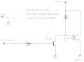
I've got this circuit for turning solar panels on/off in order to charge a battery (or run a pump). This works but what I really want to do is PWM the panel so I can hold the battery voltage exactly where it needs to be for a multi-stage charger. The panel can put out as much as 22V.
I ran into an overheating problem with a previous MOSFET circuit and I'm wondering if my 10K and 20K resistor choices off the mark if I want to switch this at 1Khz to 5Khz. The RC created by the 20K and P-MOSFET gate looks like it will slow down the switching. I'm always leaking current when the P-MOSFET conducts, so I don't want to leak any more energy than I have to. Any ideas on how better to do this? Thanks!
Attachments
-
 5.7 KB Views: 215


