Facebook
 Google
 GitHub
 Linkedin
Hi there -
Since everyone was so helpful with my last question, I was hoping I could get a little guidance about a problem I'm currently trying to solve.
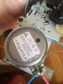
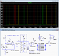
I'm using the attached circuit with the intention of creating variable-speed control on some consumer cassette tape players. As of right now, it seems that the behavior is much more binary - the motor turns on and off, depending on the pulse-width, without much variability of speed. This is surprising to me because the circuit works quite well on some isolated brushed DC motors I had, laying around.
Can anyone make some suggestions? Thank you.
Since everyone was so helpful with my last question, I was hoping I could get a little guidance about a problem I'm currently trying to solve.
I'm using the attached circuit with the intention of creating variable-speed control on some consumer cassette tape players. As of right now, it seems that the behavior is much more binary - the motor turns on and off, depending on the pulse-width, without much variability of speed. This is surprising to me because the circuit works quite well on some isolated brushed DC motors I had, laying around.
Can anyone make some suggestions? Thank you.
Attachments
-
 57.6 KB Views: 20
")