Assistance requested - Aux input for Becker Audio30 BM3309 Head unit via Cassette player ..#2

Thread Starter

Gogu48

Joined Jan 13, 2023
4
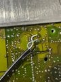
Hello everyone, i have a BE3307, I assume the approach would be similar. Mine has only tape and my car doesn't have a cd-changer unit. Do you know if i can do this mod on the CD line and be able to switch to the cd input ? I tried to solder an aux line on CASS_L and CASS_R on the end side of the capacitor (not the one with continuity to the chip) with a 10kOhm resistor, but even with my tape on I couldn't hear a thing. Do I need a dummy tape or get rid of the resistors ?

Mod: link to old thread
https://forum.allaboutcircuits.com/...-unit-via-cassette-player.206610/post-1982196
1774356098188.png
 
Last edited by a moderator:

Loreani

Joined Mar 23, 2026
7
I ran into something very similar on mine. Tapping into CASS_L / CASS_R didn’t work for me either - no sound at all. Turned out I was basically feeding signal into the wrong part of the circuit.
 

0ri0n

Joined Jan 7, 2025
160
Do you know if i can do this mod on the CD line and be able to switch to the cd input ?

You would also have to tell the audio controller over the I2C bus to switch to the CASS_L/R inputs.


I tried to solder an aux line on CASS_L and CASS_R on the end side of the capacitor (not the one with continuity to the chip) with a 10kOhm resistor, but even with my tape on I couldn't hear a thing.

The NFCCL/R (CD_LP/RP @ audio controller) lines are usually used for the tape deck audio.


Do I need a dummy tape or get rid of the resistors ?

Yes, you probably need a dummy tape (try removing the reel?) unless you find out how to fake that and make the main processor believe a tape is inserted an running.
 

Thread Starter

Gogu48

Joined Jan 13, 2023
4
Great, thank you a lot. i will buy a dummy tape.

I've also found a "master pdf" which contains the schematics. With this I was able to understand that NFCCL and NFCCR have a bottom connection to the other side of the place on chip XA2510.

Like @gavitron said here ,
https://forum.allaboutcircuits.com/...-bm3309-head-unit-via-cassette-player.206610/

"I just tried this mod on my BE3309, and I discovered that there are three test pads for tape audio right behind the tape-assembly connector. On the schematic, part 15, they are marked as MP701, MP702, and MP703, and expose NFCCL, NFCCR, and GND respectively. I soldered a 3-wire headphone socket to these pads, and I can hear audio from an aux-in source, but it is quite attenuated. should I be able to simply replace the 3K9 resistors with 0-ohm solder bridges, or do I have to pull the 8K2 resistors as well? (R426 thru R429)"

I've found the places on the backplate and soldered an aux to the back of the device. Now the sound passes.

I will continue with my project, add BT device to this aux and see how it sounds in my car. If sound is "attenuated" then I will try bridge-solder R426/R428 like mentioned in the 1st forum article.
1774370794808.png
 

Attachments

gavitron

Joined Feb 7, 2026
2
I ran into something very similar on mine. Tapping into CASS_L / CASS_R didn’t work for me either - no sound at all. Turned out I was basically feeding signal into the wrong part of the circuit.
I think it was 0ri0n in the other thread who noticed that Becker decided to use CASS_* for CD input, and CD_* for tape on the TDA7340G. They also feed the Weather band decoder into AMR and AM Radio into the PHONE_* input, I think only FM radio is "correctly" wired per the datasheet.

Gogu48, my stereo came with a tape forgotten in the unit, so I just unscrewed the cassette's case, and took out the spools, then put it back together, for a free dummy tape. if you have the time, you can find cheap-or-free cassettes at almost any thrift store.

one thing I'll note about my mod so far: Because the audio levels from my BT unit are so low, I have to push all the volume controls to max (BT + Radio) but that much gain also amplifies a lot of EMI, and can be quite distracting/annoying. I've read somewhere that cutting the traces to the actual cassette unit can eliminate some of that EMI, but it's also possible that my hack-job on the R/C's is to blame.

I've been trying to track down more info about the cassette mechanism itself, I've found the service manual for the Alpine GR71, but they never published this specific circuit layout. I've been thinking that it should be possible to pull out the entire cassette mech, and "fake" the tape-in signal back to the head-unit, leaving the audio pins on the ST701 header available for input. It should be possible even, to tie REEL_R,REEL_F to a "decent" (or DIY) BT module, so that you'd get native track skip. screencap 2026-03-24 at 11.37.31 AM.png
 

Thread Starter

Gogu48

Joined Jan 13, 2023
4
From what I’ve read from Calude and ChatGpt, i think I can listen to the oscilating signal from both reels, via arduino or rpi, and try to replicate it. I will do it tomorrow if I manage to find some free time.
I think these are the only pins needed from st701 in order for the main board to work in tape mode without the tape mechanism.
 

Thread Starter

Gogu48

Joined Jan 13, 2023
4
@gavitron , @0ri0n , I managed to succeed, at least on a medium level.
I will let you know how I did it;
  • I measured the ST701 pins on different states using an arduino (with tape attached and tape detached)
  • I tried to replicate the signals, but no luck, probably because there is some kind of communication between uP or IC701(CXA2511Q) and some pins from ST701
  • After that I de-soldered the big motor on the tape mechanism
  • I listened to the states again to see what was the trigger signal. I learned that CCPSE and CCMOT are doing something over there

For measuring I used an arduino script (ST701 see attached .ino file) to do SerialPrinting and a python script to generate these picture and csv files. See them down below.
Initially I tried to a pulldown on CCPSE with arduino then try to simulate reels with the TAPE detached but no luck. Now seeing these pictures again, I thing the CCLDG is the 1st signal, not CCPSE, but I'm already sick of how much time spent on this in order to make stereo line work.

After that I de-soldered the motor and added a change detection on CCPSE + CCMOT which triggered reel generation on REEL_L and REEL_R. With a few updates I managed to make it work. Finally I migrated the code from arduino to an AtTiny85 (Reel_digispark.ino file).

FINAL RESULT - you press tape, the tape is verified that is inside, the added chip triggers reel generation and the stereo line works without the tape rotating. Script works in a manner in which you can change back to fm and to tape without faults.

Injection points for the stereo, on the back-side of the PCB.
1775223374733.png

Measure_all_motor_on.png

Measure_all_TAPE_disconnected.png

Measure_all_TAPE_on_motor_desoldered.png
 

Attachments

Top