I don't understand how current is unlimited when that capacitor is not directly connected to the battery. I may look into a series resistor for higher voltages.
Also, I think from now on, for the VU meter transistors, I'm gonna put in a diode (cathode to base, anode to ground) at the points where -6V is reached. Then again, that would only be necessary if I tried 14V again.
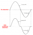
I just ran a test with 7.2V supply for say 20 minutes and I didn't notice any heat, and I had the input volume cranked to about 80%. Distortion happened after that. I guess that's the price I have to pay for low voltage, but that's less expensive than overheating/damaging parts.
Also, I think from now on, for the VU meter transistors, I'm gonna put in a diode (cathode to base, anode to ground) at the points where -6V is reached. Then again, that would only be necessary if I tried 14V again.
I just ran a test with 7.2V supply for say 20 minutes and I didn't notice any heat, and I had the input volume cranked to about 80%. Distortion happened after that. I guess that's the price I have to pay for low voltage, but that's less expensive than overheating/damaging parts.