Overdrive Circuit

Thread Starter

DanBest

Joined Sep 28, 2023
4
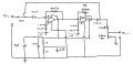
I have attached an image of an overdrive circuit that I have designed for a guitar pedal. I have built the circuit and it isn’t working and I wanted to find out if there were any obvious design flaws/things I need to change or consider? I’m new to signal processing.
The first potentiometer is meant to control the gain of the signal and introduce clipping whereas the second potentiometer is intended to control volume of the output signal.
 

Attachments

AnalogKid

Joined Aug 1, 2013
12,045
I have built the circuit and it isn’t working
What does that mean? Is it totally dead, is it amplifying but not clipping, is it picking up old Star Trek reruns?

To start with, the virtual ground *must* be decoupled at all audio frequencies of interest. As it is, it looks like a 500 ohm resistor to GND and all signals connected to it interact. As a starting point, use a 100 uF electrolytic and 0.1 uF to 1.0 uF ceramic in parallel.

Also, add a 0.1 uF ceramic capacitor at each opamp's power pins. Place it (them) close to the device pins, and the leads as short as possible.

There is no DC path to GND for the first opamp. The non-inverting input must have a DC voltage to establish an operating point for the input stage. A 0.33 uF cap to GND will form an input highpass filter with a corner frequency of around 5 Hz.

Due to the feedback components used, each stage is acting as a highpass filter with a corner frequency of 16 Hz. The two stages combine such that the frequency response at 16 Hz is down 6dB from "flat", and down 3 dB at 32 Hz. We don't know what your bandwidth requirements are, so this may or may not be an issue.

Also, please add unique reference designators to each component, pin numbers on the opamps, and repost. Without this, discussing the performance of individual components is . . . difficult.

ak
 
Last edited:

Audioguru again

Joined Oct 21, 2019
6,826
The +input of the first opamp is missing an extremely important bias resistor (1M) to the virtual ground.
Without knowing the opamp part number we do not know if yours works with a supply that is only 9V (dropping to 6V?) or if it works with a bias resistor of 1M.
 

Attachments

Thread Starter

DanBest

Joined Sep 28, 2023
4
What does that mean? Is it totally dead, is it amplifying but not clipping, is it picking up old Star Trek reruns?

To start with, the virtual ground *must* be decoupled at all audio frequencies of interest. As it is, it looks like a 500 ohm resistor to GND and all signals connected to it interact. As a starting point, use a 100 uF electrolytic and 0.1 uF to 1.0 uF ceramic in parallel.

Also, add a 0.1 uF ceramic capacitor at each opamp's power pins. Place it (them) close to the device pins, and the leads as short as possible.

There is no DC path to GND for the first opamp. The non-inverting input must have a DC voltage to establish an operating point for the input stage. A 0.33 uF cap to GND will form an input highpass filter with a corner frequency of around 5 Hz.

Due to the feedback components used, each stage is acting as a highpass filter with a corner frequency of 16 Hz. The two stages combine such that the frequency response at 16 Hz is down 6dB from "flat", and down 3 dB at 32 Hz. We don't know what your bandwidth requirements are, so this may or may not be an issue.

Also, please add unique reference designators to each component, pin numbers on the opamps, and repost. Without this, discussing the performance of individual components is . . . difficult.

ak
Thanks for all the help. I have thrown together a quick schematic with all the part labels (attached below).
 

Attachments

Audioguru again

Joined Oct 21, 2019
6,826
Your new schematic is still missing the very important bias resistor I show in post #3.
The old LM833 was designed for a 47k ohms phono cartridge (remember vinyl records?) not a guitar pickup that needs a Jfet opamp with at least 1M ohms.
 

Thread Starter

DanBest

Joined Sep 28, 2023
4
Your new schematic is still missing the very important bias resistor I show in post #3.
The old LM833 was designed for a 47k ohms phono cartridge (remember vinyl records?) not a guitar pickup that needs a Jfet opamp with at least 1M ohms.
Thanks for the help I have only just recently started covering op amps at uni so I don’t know a whole lot about them yet. I’ll add the bias resistor in and see if I have any luck cheers
 

Thread Starter

DanBest

Joined Sep 28, 2023
4
Your new schematic is still missing the very important bias resistor I show in post #3.
The old LM833 was designed for a 47k ohms phono cartridge (remember vinyl records?) not a guitar pickup that needs a Jfet opamp with at least 1M ohms.
I have added the bias resistor and while doing so noticed that I forgot to reconnect the input signal to the coupling capacitor when I made a change to the circuit earlier… whoops.
The pedal works now, just sounds terrible.
 

Ian0

Joined Aug 7, 2020
13,097
Your circuit is an “overdrive” circuit, not a distortion circuit. It is designed to amplify the signal linearly, so that the higher signal voltage drives the power amplifier into clipping to produce a distorted sound.
The distortion is therefore produced by the power amplifier, not your circuit - your circuit will have little or no influence on what it sounds like.

By the way, 1MΩ, although traditionally used, is bit too high. If you model with pickup as 6kΩ in series with 6H, and add a couple of hundred pF of cable capacitance, you will get a huge resonance peak in the 1kHz to 10kHz region (depending on the cable length). 100k input impedance avoids that, without losing treble.
 

Audioguru again

Joined Oct 21, 2019
6,826
The overdrive circuit in this thread now has a diode in series with its output that will rectify the audio making awful noises. Without the output diode this opamps circuit can produce "overdrive distortion". All overdrive pedal circuits in Google use diodes and high preamp gain to produce clipping distortion.

Jimi Hendrix used the Fuzz Face distortion circuit on a pedal with his electric guitar.

All electric guitar amplifiers used a 1M input resistance (with a vacuum tube) to produce a resonant high frequency peak since the speakers had a poor high frequency response and maybe the users had high frequency deafness from the very loud sounds.
 
Top