Output Impedance for Differential Amp -- Error in Book?

Thread Starter

100

Joined Oct 10, 2010
2
Hey. On this topic, my book doesn't even derive the equation! It simply says, "if Vid is set to zero, then gmv3 and gmv4 are zero, and the differential-mode output resistance Rod is equal to

Rod = 2(Rc||ro)"

I do not agree with their answer. I've attached my own analysis where I calculated a value 1/4 of theirs. What's going on here? It's definitely not a single typo, because every place the book calculates Rod, it uses that equation.

analysis:
 
Last edited by a moderator:

Georacer

Joined Nov 25, 2009
5,182
I 'm not sure about it, but I think the meaning of output resistance is the equivalent resistance that you find when you start from the first pin and make your way to the other.

In this case, your way goes through ground. So you will start from the left pin, go to the ground through Rc||ro and make your way to the right pin through another Rc||ro, thus Rod=2Rc||ro.
 

Ghar

Joined Mar 8, 2010
655
The equivalent circuit you drew gives you 2(Rc||ro), not 0.5.

Mentally connect all the ground nodes together and forget about that symbol.
You have ro||Rc in series with ro||Rc

Also, I might be wrong since I haven't done this in a while but the emitters aren't at small signal ground.
Once you open circuit the current source they are simply connected, but are not at ground.
Hence Rc go to ground but not ro. So technically the resistance isn't 2(Rc ||ro) but rather (2Rc) || (2ro)
Those expressions are equal so it doesn't affect the result.
 
Last edited:

Thread Starter

100

Joined Oct 10, 2010
2
The equivalent circuit you drew gives you 2(Rc||ro), not 0.5.

Mentally connect all the ground nodes together and forget about that symbol.
You have ro||Rc in series with ro||Rc

Also, I might be wrong since I haven't done this in a while but the emitters aren't at small signal ground.
Once you open circuit the current source they are simply connected, but are not at ground.
Hence Rc go to ground but not ro. So technically the resistance isn't 2(Rc ||ro) but rather (2Rc) || (2ro)
Those expressions are equal so it doesn't affect the result.
ahh of course. yes, they are in series instead of parallel. thanks. I ran a simple spice simulation too to be extra sure, and sure enough, they are in series.
 

The Electrician

Joined Oct 9, 2007
2,986
Hey. On this topic, my book doesn't even derive the equation! It simply says, "if Vid is set to zero, then gmv3 and gmv4 are zero, and the differential-mode output resistance Rod is equal to

Rod = 2(Rc||ro)"

I do not agree with their answer. I've attached my own analysis where I calculated a value 1/4 of theirs. What's going on here? It's definitely not a single typo, because every place the book calculates Rod, it uses that equation.
This is an interesting post. It shows how careful one must be when analyzing differential circuits.

It appears that you have proceeded by determining the output impedance of each side of the diff amp separately and then doubling that value (originally you took 1/2 the separate impedances, but you have now realized the error of that).

The first error occurs in your determination of the output impedance at a single one of the collectors. The impedance of a single node in a circuit with respect to the reference node (often called ground) is properly called a "driving point impedance" (a single ended impedance), especially if there will be a subsequent need to distinguish it from a "differential impedance".

The result you have for the driving point impedance at each collector, Rc||ro, is incorrect. The presence of an emitter resistor, RE, complicates things.

In an older thread, I described a method whose excellent exposition is due to Jacob Shekel; see:

http://forum.allaboutcircuits.com/showthread.php?t=26710

In that thread I show how to create an admittance matrix with transistors plus passive elements.

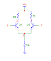
I've followed that procedure and created an admittance matrix for a two transistor differential amplifier. Besides the external resistors, RE and Rc, I have included ro, the internal collector resistance, and re, the internal emitter resistance.

The first attached image shows the circuit with the 5 relevant nodes numbered. The rows and columns of the admittance matrix correspond to the nodes in the column, that is, row 1 and column 1 correspond to node 1, etc.

Following the procedure explained in the earlier thread, after the admittance matrix (Y matrix) is set up, it in inverted giving an impedance matrix (Z matrix), from which the various circuit properties can be conveniently derived.

The diagonal elements of the Z matrix are the driving point impedances (single ended impedance from a single node to ground) of the 5 nodes.

It can be seen that the single ended output impedances at each collector are much more complicated than just Rc||ro. This is for the case where the input nodes are NOT grounded; they are just floating (for small signals; the DC bias arrangement must still be in place).

When using the admittance matrix method, it's easy to derive the matrix for the circuit when node(s) are grounded; you just delete the row and column for the grounded node. To derive the Y matrix for this circuit with inputs grounded (for small signals), we just delete the first and fifth rows and columns; then we invert to get the Z matrix for the grounded input case. When we do this, there are only 3 nodes left--the two collectors and the emitters/RE junction.

Having done this, we can see that the expressions for the driving point impedances at the individual collectors (single ended output impedance) again is much more complicated than just Rc||ro.

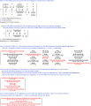
The calculations so far are shown in the second attached image.

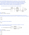
The third image shows the calculation for differential output impedance.

Two determine the DIFFERENTIAL output impedance, we must calculate the difference in the voltages that appear at the two outputs when they are driven by a FLOATING current source.

The second image shows how this is done. We apply a current of 1 amp at node 2 and another current of -1 amp at node 4. We then solve the network for the voltages at the 5 nodes of the circuit, and subtract the voltage at node 4 from the voltage at node 2, divide by 1 amp, and this gives us the differential output impedance. This is for the case where the two inputs are NOT grounded. The result is 2(Rc||ro). This is very different from the driving point impedance (single ended impedance) at the individual collectors.

To solve for the case where the inputs are grounded, the first and fifth rows and columns are deleted from the admittance matrix, and a floating current source is once again applied to the two collectors. Surprisingly, the differential output impedance is also 2(Rc||ro) with the inputs grounded.

I have included re and β in my calculations, which you didn't in yours. If you let re->0 and β->∞ you can get simplified expressions which would be good enough for most circuit analysis problems. However, even having done that, the single ended output impedances are more complicated than Rc||ro. Edit: The expression for the single ended output impedance with re->0 and β->∞ is Rc||ro + (Rc^2)/(2(Rc+ro)). The extra term after the Rc||ro is caused by the emitter coupling due to a non-zero RE.

It's interesting that the differential output impedance when calculated fully with re and β included in the admittance matrix doesn't involve re, RE, or β even though the single ended impedances do.

By a very happy circumstance, you got the correct differential result even though your method of calculating it is incorrect.

The correct calculation is complicated; maybe that's why the book didn't show the derivation.
 

Attachments

Last edited:

The Electrician

Joined Oct 9, 2007
2,986
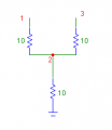
A simple example to see why you can't find a differential impedance by just adding two single ended driving point impedances can be seen by considering the little circuit shown in the attachment.

If you measure the impedance from node 1 to ground, and from node 3 to ground you get 20Ω for each of them. Adding the two would lead one to believe that the differential impedance is 40Ω.

Yet, clearly, if one connected an ohmmeter between nodes 1 and 3, the impedance is just 20Ω, not 40Ω.

Differential impedance must be calculated by stimulating the two nodes with a floating current source, or some similar method.
 

Attachments

anhnha

Joined Apr 19, 2012
904
A simple example to see why you can't find a differential impedance by just adding two single ended driving point impedances can be seen by considering the little circuit shown in the attachment.

If you measure the impedance from node 1 to ground, and from node 3 to ground you get 20Ω for each of them. Adding the two would lead one to believe that the differential impedance is 40Ω.

Yet, clearly, if one connected an ohmmeter between nodes 1 and 3, the impedance is just 20Ω, not 40Ω.

Differential impedance must be calculated by stimulating the two nodes with a floating current source, or some similar method.
I always wonder why the 10 ohm tail resistor doesn't affect the different resistance.
In the circuit you post, what is the meaning of ground?
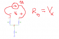
Normally to test for the input impedance I will apply a current source 1 amp between node 1 and 3 and then calculate the response voltage Vx.
The input impedance is then Vx/1amp which is also Vx.
However, the the case as in the picture below, I am confused by the ground. Why there is no current flowing through the 10 ohm tail resistor?
upload_2018-2-3_19-15-29.png
 

The Electrician

Joined Oct 9, 2007
2,986
I always wonder why the 10 ohm tail resistor doesn't affect the different resistance.
In the circuit you post, what is the meaning of ground?
Normally to test for the input impedance I will apply a current source 1 amp between node 1 and 3 and then calculate the response voltage Vx.
The input impedance is then Vx/1amp which is also Vx.
However, the the case as in the picture below, I am confused by the ground. Why there is no current flowing through the 10 ohm tail resistor?
View attachment 145068
Ground is the reference node, and it may be actually connected to the earth. Or it may be the metal case containing an electrical device such as a television or a computer. If the case is plastic there will still be a ground plane which is part of the printed circuit board: https://en.wikipedia.org/wiki/Ground_plane

See: https://en.wikipedia.org/wiki/Ground_(electricity)

In the three resistor example circuit there is no current in the tail resistor because there is no connection of your current source to the bottom of that resistor which is also the circuit ground, or reference node in this case.

Think about how you would have to connect your current source to measure the impedance from node 1 to the bottom of the tail resistor (ground in this case).
 

anhnha

Joined Apr 19, 2012
904
I was confused by ground symbol as a reference node (usually negative side of the DC voltage source). So I thought, there are somehow a closed path for current to flow through the tail resistor through that ground --> DC voltage source --> positive side of the voltage source.

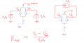
With the setup for output impedance above, are the two methods below equivalent?

upload_2018-2-4_1-29-22.png
 

The Electrician

Joined Oct 9, 2007
2,986
In your image, the situation on the left is not using floating sources; the sources are connected to ground. For this circuit, because of the perfect symmetry of the circuit, identical Q1 and Q2, the same collector resistor Rc for the two transistors, etc., the left hand arrangement will give the same result because no current flows in RE. But if you have a circuit without the perfect symmetry you might not get the same result with the left hand arrangement as with the right hand arrangement. If this arrangement were used with the 3 resistor example earlier, no current would flow in the tail resistor, again because of the perfect symmetry; the two currents of +1 amp and -1 amp would cancel in the tail resistor.

I'll have to think about the case without perfect symmetry using the left hand arrangement later today.

The right hand connection method is correct method to use in all cases for determining differential impedance; the source is floating. The word "floating" in circuit theory means that there is no connection to the reference node which is "ground" in this case.
 

anhnha

Joined Apr 19, 2012
904
The right hand connection method is correct method to use in all cases for determining differential impedance; the source is floating. The word "floating" in circuit theory means that there is no connection to the reference node which is "ground" in this case.
This is actually what I was confused by post 10. So the two connection methods came up.

Two determine the DIFFERENTIAL output impedance,we must calculate the difference in the voltagesthatappear at the two outputs when they aredriven by a FLOATING current source.
 

The Electrician

Joined Oct 9, 2007
2,986
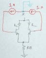
Here's a diagram to make it easier to understand what's going on:

DiffPic.jpg

At the node designated X we can apply Kirchoff's current law. We have 1 amp entering the node from the right and 1 amp leaving the node from the left. These two currents add to zero, so there cannot be any current in the green wire going to ground. Therefore that wire has no effect and we can remove it. Then we would have two 1 amp current sources in series and they can be replaced with one current source of 1 amp. Thus the result of the two current sources is exactly the same as the single floating source, and the circuit doesn't have to be perfectly symmetrical to give the same measurement in both cases. However, I think it's easier to understand by using the floating source.

There is one point when using the two sources that's crucially important. To obtain the differential impedance, both sources have to be connected and the measurements at the two collectors must be made at the same time. We can't, for example, connect the left source (without the right source connected) and measure the impedance there (calling it ZL), then connect the right source (disconnecting the left source) measure the impedance there (calling it ZR), and then believe that (ZL-ZR) is the differential impedance between the two collectors.

This is because when the left source (for example) is connected, it not only causes a voltage to appear at the left collector, but it also causes a voltage at the right connector due to the non-zero transfer impedance between the left and right collectors, and similarly when the source is connected to the right collector.
 

anhnha

Joined Apr 19, 2012
904
I've got it now. Thanks.
In your diagram, you inject 1 amp floating current source into base terminal of transistors. I think this is just an example to show the symmetrical case.
Also, I think the setup is for differential input impedance measurement and Rin = 2*re*(β+1) with assumption that infinite output resistance ro-> ∞.
 
Top