 Facebook
 Google
 GitHub
 Linkedin
Indeed. Trying to get there.Has the thought occurred to you that the buffer resetting might actually solve your problem? Putting it off until later might prevent you from finding an easy solution?
Oshonsoft programs with INTERRUPTS and PARSE
- Thread starter camerart
- Start date
Scroll to continue with content
Hi D,Has the thought occurred to you that the buffer resetting might actually solve your problem? Putting it off until later might prevent you from finding an easy solution?
Yes, it has, and I've tried with and without, with no difference apart from using time, from what I can see.
C.
Hi JT,Can you post the old program that had the radio working? A look at it may be helpful.
Agreed that we can wait on more changes until you drill down into the radio error.
I asked the question about a delay between radio messages because if you change a channel when the data stream is active, that can generate UART errors. With the working channels at 5/sec, there is a good possibility that you are lucky enough to hit between messages most of the time. If there is little or no delay between the messages, the chances of jumping into the middle of a message increase and with that the probability of mis-handled errors increases too.
The DATASWITCH should only switch after the last message has been PARSED, and all of the STRING has been processed. I've also added a [WAITMS 500], as a test.
Here is the old program, where everything is working, but not well:
As mentioned 3x peripherals come through the DATASW RX, and 2-3x through SPI, in the above program 5x are working, the '5110' screen is not switched on.
The radios have always worked, but this issue is with the PCB-Radio-RX, which does work in the above program. Note: I moved the DATASW operation about.
I've tried testing with the DATASWITCH only pointing to REMOTE, but it still READS GPS and 4431 This could be an error on my part.
I've also added the last INTERRUPT-PARSE program again, that I've just checked on the simulator. I've tidied it up a bit.
I won't change anything myself, without a suggestion from the forum. Hopefully, there will be fewer misyakes this way: )
Cheers, C.
Attachments
-
26.3 KB Views: 4
-
7.1 KB Views: 2
Hi JT,I’ll take a peek.
Can you also post a link to your current schematic or just repost it here? Both ends.
Here is a link: https://forum.allaboutcircuits.com/...-pic-in-oshonsoft.148795/page-35#post-1493488 #699 also note #700.
What does "both ends" mean?
C
Hi JT,Both ends means both ends of the radio link. I think I need to review your project in detail. My misunderstandings are causing confusion.
Me too
")
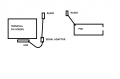
Here's a representation of the PCB to Terminal screen. also a Terminal view:
The computer Terminal transmits a TEST imitating the REMOTE, sentence [$REMOTE,11,22,33,WXX] from a MACRO Note $ and W.
The terminal also receives the PCB transmissions.
The attached Terminal view, shows: it's transmitting $ sentence. the received Joystick positions, the GPS READing, the result of the $sentence after PARSE, the Temperature and pressure, the PCB compass READing and the Reading from the INCREMENTAL ENCODER on the Transmitter.
Note the result of the $ Sentence is a long way behind it's transmission. Remember this is the OLD program.
C
Attachments
-
 8 KB Views: 4
 -
 106.4 KB Views: 4
Let's start with the stripped down one..
Other issues:
You enable interrupts before configuring the serial port.. configure first, enable last. Consider what happens if you get an interrupt before initializing the buffer and index.
EDIT: Ignore comment re: RCIP=1
IMHO, you won't get much further until you fix the interrupt error handling. I don't think it's possible with your scheme to switch channels without generating some errors and you're not handling them.
I purchased OSH so that I can follow along. If you want to proceed with straightening this out in a structured, orderly manner we can take a shot at that. Much of what others brought up in these threads will apply so think about that. I really don't see any way other than dumb luck to get to success otherwise.
Thoughts?
REMOTE ONLY:
'18LF4620 8MHz XTL BASE PCB_4 INT_PAR REMOTE only 300620 0900
Define CONFIG1L = 0x00
Define CONFIG1H = 0x02  '0x02 =EXT 8MHz
Define CONFIG2L = 0x1e
Define CONFIG2H = 0x00
Define CONFIG3L = 0x00
Define CONFIG3H = 0x81  'Set for HVP
Define CONFIG4L = 0x80
Define CONFIG4H = 0x00
Define CONFIG5L = 0x0f
Define CONFIG5H = 0xc0
Define CONFIG6L = 0x0f
Define CONFIG6H = 0xe0
Define CONFIG7L = 0x0f
Define CONFIG7H = 0x40

Define SIMULATION_WAITMS_VALUE = 1  'Comment in for SIM out for PIC
Define CLOCK_FREQUENCY = 8
Define SINGLE_DECIMAL_PLACES = 2
Define STRING_MAX_LENGTH = 40
'SET PIN IN/OUT
TRISA = %00000000
TRISB = %00000000
TRISC = %10000000  '7 = RX
TRISD = %00000000
TRISE = %00000000
'SET BITS ON/OFF
PORTA = %00000000  'ON/OFF
PORTB = %00000000
LATB = 0
PORTC = %00000000
PORTD = %00000000
PORTE = %00000000  'POSS MCLR RE3
WaitMs 10

'set up interrupts
RCON.IPEN = 1  '%10000000 Int Priority Enable bit 'This MUST be included when using Interrupts (Priority HIGH/LOW)[#189 hserin blocking]
PIE1.RCIE = 1  '%00100000 EUSART Receive Interrupt Enable bit [ 1=en ]
INTCON.PEIE = 1  '%01000000 Peripheral Interrupt Enable bit
INTCON.GIE = 1  '%10000000 Global Interrupt Enable bit
''BAUDCON.BRG16 = 1  '%00001000  1 = 16-bit Baud Rate Generator – SPBRGH and SPBRG
TXSTA.SYNC = 0  '%00010000 = Asynchronous mode
RCSTA.SPEN = 1  '%10000000  1 = Serial port enabled (configures RX/DT and TX/CK pins as serial port pins)
RCSTA.RX9 = 0  '%01000000  0 = Selects 8-bit reception
RCSTA.CREN = 1  '%00010000  1 = Enables receiver

'Read the 8-bit received data by reading the RCREG register.
'If any error occurred, clear the error by clearing Enable Bit, CREN.
'If using interrupts, ensure that the GIE And PEIE bits in the INTCON register(INTCON < 7: 6 >)

Symbol yled = LATE.1
Symbol rled = LATE.2

'START UP LEDS
yled = 1
rled = 1
WaitMs 1000
yled = 0
rled = 0
WaitMs 1000

'**** Setup Hw USART ****
Hseropen 9600
Hserout "READY", CrLf

Dim char As Byte
Dim buf(50) As Byte  '*** received message comes to buf
Dim rxin As Byte  'ïndex To buf
''Dim cnt As Byte
Dim msg_rdy As Bit
Dim err As Bit  'Errors in receiving $DATA

'GPS and REMOTE
Dim strchr As String  'GPGGA or $REMOTE msg
Dim sinlat As Single  'For calculation
Dim sinlong As Single  'For calculation
Dim strtim As String
Dim strlat As String
Dim strlong As String
Dim cnt As Byte  'CHARs counted through buf
Dim strbuf As String
Dim buf_fill As Bit  'Message loading
Dim buf_done As Bit  'Buffer $ to W   1 = Done 0 = Not
Dim prs_fill As Bit
Dim prs_done As Bit  'Empty Buffer now, it has been READ.   as 1 = Don
Dim rxpsn As Byte
Dim rxsize As Byte
rxsize = 49

'Dim csv As Byte
Symbol dataswitch_S0 = LATD.5  'C/S S0=L S1=L =TX4431,  S0=L S1=H =HC-12, S0=H S1=L =GPS
Symbol dataswitch_S1 = LATD.6
Dim datasw As Byte  'For setting next in sequence of DATASWITCH
datasw = 0  '1st in sequence GPS

'PIC18F4431
Dim qeideg As String

'REMOTE from distance
Dim remvolt As Byte
Dim strremvolt As String
Dim remalt As Byte
Dim strremalt As String
Dim remdist As Byte
Dim strremdist As String

'HC-12 RADIO
Symbol radset = LATD.4  'HC-12 0=COMMAND ON 1=DATA ON

'INITIALISATION
'PRESS BUTTON (OR RADSET)
radset = 0  'SET HC-12 COMMAND ON
WaitMs 100
Hserout "AT+C002", CrLf  '433.800
WaitMs 100
radset = 1  'SET HC-12 RUN ON
WaitMs 100

rxin = 0
msg_rdy = 0

Enable High

main:  '/\/\/\/\/\/\/\/\/\/\/\/\/\/\/\/\/\/\/\/\/\/\/\/\/\/\/\/\/\/\/\/\/\/\/\/\/\/\/\

If buf_done = 1 Then
    buf_done = 0  'Buf filled
    prs_fill = 1
    Gosub parse
    prs_fill = 0
    prs_done = 1  'Parse Done
Endif

If prs_done = 1 Then
    strbuf = ""
    '...SET DATASWITCH: 'S0=1 S1=0 =TX4431,  S0=0 S1=H =HC-12, S0=0 S1=0 =GPS
    Gosub switch
    'To avoid A framing error, you are best To !!switch dataswitch!! between Ascii characters
    'by checking BAUDCON.RCIDL=1. If it is =1,
    'Then the UART is idle And Not receiving any serial data stream.
    'If BAUDCON.RCIDL = 1 Then  'Avoid framing error-BIT6 NEVER 1! in SIM
        'rled = 1
        'yled = 1
        WaitMs 500  '//////////////////////////////////////////////
        RCSTA.CREN = 1  'INTERRUPT ENABLED
        PIE1.RCIE = 1  'ENABLEs EUSART RECEIVE INTERRUPT
        cnt = 0
        rxpsn = 0
        prs_done = 0  '!!!!!!!!!!!!!!!!!!!!!!!!!!!
    'Endif
Endif

If Len(strtim) <> 0 Then  'if string is zero length don't hserout........
    Hserout "T=", strtim, " N=", strlat, " W=", strlong, CrLf
    'WaitMs 5  '????????????
Endif

If Len(qeideg) <> 0 Then
    Hserout "QEIDEG=  ", qeideg, CrLf  'QEIDEG=BASE 4431 Opto encoder
    'WaitMs 5  '??????????
Endif

If Len(strremvolt) <> 0 Then
    Hserout "REMVOLT=", strremvolt, " REMALT=", strremalt, " REMDIST=", strremdist, CrLf
    'WaitMs 5  '??????????
Endif
'INTCON.GIE = 1  '!!!!!!


Goto main
End
On High Interrupt
Save System


'BIT1..if over run error then flush RXD buffer
'BIT2..framing error(can be cleared by reading RCREG register And receiving Next valid Byte)
If RCSTA.OERR = 1 Or RCSTA.FERR = 1 Then
    RCSTA.CREN = 0
    RCSTA.CREN = 1  'BIT4 ENABLES RECEIVER
    char = RCREG  '1
    char = RCREG  '2
    err = 1  'ERROR
Endif

If PIR1.RCIF = 1 Then
        char = RCREG
        If char = "$" Then
            rxpsn = 0
            buf_fill = 1
        Endif
        If buf_fill = 1 Then
            buf(rxpsn) = char
            If rxpsn < 50 Then
                rxpsn = rxpsn + 1
            Endif
        Endif
        If buf(0) = "$" And char = "W" Then
            RCSTA.CREN = 0  'INTERRUPT DISABLED
            PIE1.RCIE = 0  'DISABLEs EUSART RECEIVE INTERRUPT
            buf_fill = 0
            buf_done = 1
        Endif
Endif
Resume
parse:
'These subrs' extract the main values from the GPS,REMOTE and QEIDEG strings, into named value messages
'also converts the strings to a named numeric values, for maths
For cnt = 1 To rxpsn
    char = buf(cnt)
    strchr = Chr(char)
        strbuf = strbuf + strchr
        If buf(5) = "C" Then  '0 in DATASWITCH sequence
            strtim = MidStr(strbuf, 7, 2) + ":" + MidStr(strbuf, 9, 2) + ":" + MidStr(strbuf, 11, 2)
            strlat = MidStr(strbuf, 19, 10)  'POSITION_Number of digits in the STRING
            strlong = MidStr(strbuf, 33, 8)
            datasw = 1
        Else
            If buf(1) = "R" Then  '1 in sequence
                strremvolt = MidStr(strbuf 8, 2)
                strremalt = MidStr(strbuf 11, 2)
                strremdist = MidStr(strbuf 14, 2)
                datasw = 2
            Else
                If buf(1) = "Q" Then  '2 in DATASWITCH sequence
                    qeideg = MidStr(strbuf, 8, 3)
                    datasw = 0
                Endif
            Endif
        Endif
Next cnt

Return
switch:
''SET DATASWITCH: 'S0=0 S1=0 =GPS--S0=1 S1=0 =REMOTE--S0=0 S1=1 =TX4431,

If datasw = 0 Then
    Hserout "DATASW=  ", #datasw, CrLf
    dataswitch_S0 = 0  'GPS
    dataswitch_S1 = 0
    rled = 0
    yled = 0
Else
    If datasw = 1 Then
        Hserout "DATASW=  ", #datasw, CrLf
        dataswitch_S0 = 1  'REMOTE HC-12
        dataswitch_S1 = 0
        rled = 1
        yled = 0
    Else
        If datasw = 2 Then
            Hserout "DATASW=  ", #datasw, CrLf
            dataswitch_S0 = 0  'QEI 4431
            dataswitch_S1 = 1
            rled = 0
            yled = 1
        Endif
    Endif
Endif
Break  '!!!!!!!!!!!!!!!!!!!!!!!!!!!!!!!!!!!!!!!!!
WaitMs 50  '???????????????????????
ReturnThat's because you change the channel (datasw) as a SIDE EFFECT of the parse routine then call switch at 'If prs_done = 1'. You want to strap down the channel to the REMOTE input. The problem with side effects like this is exactly what we see - you have to butcher up unrelated code to make changes. As I, and likely others along the way, have indicated above, the switching channels should be it's own routine set that does the switch when called INDEPENDENTLY of any other operation like parsing. Stuffing unrelated things together like you have here is a recipe for long nights of fruitless debugging. You will lilely find it difficult to do any changes without breaking something else because it's all smooshed together into a lumpy mass.I've tried testing with the DATASWITCH only pointing to REMOTE, but it still READS GPS and 4431 This could be an error on my part.
Other issues:
You enable interrupts before configuring the serial port.. configure first, enable last. Consider what happens if you get an interrupt before initializing the buffer and index.
EDIT: Ignore comment re: RCIP=1
IMHO, you won't get much further until you fix the interrupt error handling. I don't think it's possible with your scheme to switch channels without generating some errors and you're not handling them.
I purchased OSH so that I can follow along. If you want to proceed with straightening this out in a structured, orderly manner we can take a shot at that. Much of what others brought up in these threads will apply so think about that. I really don't see any way other than dumb luck to get to success otherwise.
Thoughts?
Last edited:
Hi JT,Let's start with the stripped down one..
==========================================================REMOTE ONLY:'18LF4620 8MHz XTL BASE PCB_4 INT_PAR REMOTE only 300620 0900 Define CONFIG1L = 0x00 Define CONFIG1H = 0x02 '0x02 =EXT 8MHz Define CONFIG2L = 0x1e Define CONFIG2H = 0x00 Define CONFIG3L = 0x00 Define CONFIG3H = 0x81 'Set for HVP Define CONFIG4L = 0x80 Define CONFIG4H = 0x00 Define CONFIG5L = 0x0f Define CONFIG5H = 0xc0 Define CONFIG6L = 0x0f Define CONFIG6H = 0xe0 Define CONFIG7L = 0x0f Define CONFIG7H = 0x40 Define SIMULATION_WAITMS_VALUE = 1 'Comment in for SIM out for PIC Define CLOCK_FREQUENCY = 8 Define SINGLE_DECIMAL_PLACES = 2 Define STRING_MAX_LENGTH = 40 'SET PIN IN/OUT TRISA = %00000000 TRISB = %00000000 TRISC = %10000000 '7 = RX TRISD = %00000000 TRISE = %00000000 'SET BITS ON/OFF PORTA = %00000000 'ON/OFF PORTB = %00000000 LATB = 0 PORTC = %00000000 PORTD = %00000000 PORTE = %00000000 'POSS MCLR RE3 WaitMs 10 'set up interrupts RCON.IPEN = 1 '%10000000 Int Priority Enable bit 'This MUST be included when using Interrupts (Priority HIGH/LOW)[#189 hserin blocking] PIE1.RCIE = 1 '%00100000 EUSART Receive Interrupt Enable bit [ 1=en ] INTCON.PEIE = 1 '%01000000 Peripheral Interrupt Enable bit INTCON.GIE = 1 '%10000000 Global Interrupt Enable bit ''BAUDCON.BRG16 = 1 '%00001000 1 = 16-bit Baud Rate Generator – SPBRGH and SPBRG TXSTA.SYNC = 0 '%00010000 = Asynchronous mode RCSTA.SPEN = 1 '%10000000 1 = Serial port enabled (configures RX/DT and TX/CK pins as serial port pins) RCSTA.RX9 = 0 '%01000000 0 = Selects 8-bit reception RCSTA.CREN = 1 '%00010000 1 = Enables receiver 'Read the 8-bit received data by reading the RCREG register. 'If any error occurred, clear the error by clearing Enable Bit, CREN. 'If using interrupts, ensure that the GIE And PEIE bits in the INTCON register(INTCON < 7: 6 >) Symbol yled = LATE.1 Symbol rled = LATE.2 'START UP LEDS yled = 1 rled = 1 WaitMs 1000 yled = 0 rled = 0 WaitMs 1000 '**** Setup Hw USART **** Hseropen 9600 Hserout "READY", CrLf Dim char As Byte Dim buf(50) As Byte '*** received message comes to buf Dim rxin As Byte 'ïndex To buf ''Dim cnt As Byte Dim msg_rdy As Bit Dim err As Bit 'Errors in receiving $DATA 'GPS and REMOTE Dim strchr As String 'GPGGA or $REMOTE msg Dim sinlat As Single 'For calculation Dim sinlong As Single 'For calculation Dim strtim As String Dim strlat As String Dim strlong As String Dim cnt As Byte 'CHARs counted through buf Dim strbuf As String Dim buf_fill As Bit 'Message loading Dim buf_done As Bit 'Buffer $ to W 1 = Done 0 = Not Dim prs_fill As Bit Dim prs_done As Bit 'Empty Buffer now, it has been READ. as 1 = Don Dim rxpsn As Byte Dim rxsize As Byte rxsize = 49 'Dim csv As Byte Symbol dataswitch_S0 = LATD.5 'C/S S0=L S1=L =TX4431, S0=L S1=H =HC-12, S0=H S1=L =GPS Symbol dataswitch_S1 = LATD.6 Dim datasw As Byte 'For setting next in sequence of DATASWITCH datasw = 0 '1st in sequence GPS 'PIC18F4431 Dim qeideg As String 'REMOTE from distance Dim remvolt As Byte Dim strremvolt As String Dim remalt As Byte Dim strremalt As String Dim remdist As Byte Dim strremdist As String 'HC-12 RADIO Symbol radset = LATD.4 'HC-12 0=COMMAND ON 1=DATA ON 'INITIALISATION 'PRESS BUTTON (OR RADSET) radset = 0 'SET HC-12 COMMAND ON WaitMs 100 Hserout "AT+C002", CrLf '433.800 WaitMs 100 radset = 1 'SET HC-12 RUN ON WaitMs 100 rxin = 0 msg_rdy = 0 Enable High main: '/\/\/\/\/\/\/\/\/\/\/\/\/\/\/\/\/\/\/\/\/\/\/\/\/\/\/\/\/\/\/\/\/\/\/\/\/\/\/\ If buf_done = 1 Then buf_done = 0 'Buf filled prs_fill = 1 Gosub parse prs_fill = 0 prs_done = 1 'Parse Done Endif If prs_done = 1 Then strbuf = "" '...SET DATASWITCH: 'S0=1 S1=0 =TX4431, S0=0 S1=H =HC-12, S0=0 S1=0 =GPS Gosub switch 'To avoid A framing error, you are best To !!switch dataswitch!! between Ascii characters 'by checking BAUDCON.RCIDL=1. If it is =1, 'Then the UART is idle And Not receiving any serial data stream. 'If BAUDCON.RCIDL = 1 Then 'Avoid framing error-BIT6 NEVER 1! in SIM 'rled = 1 'yled = 1 WaitMs 500 '////////////////////////////////////////////// RCSTA.CREN = 1 'INTERRUPT ENABLED PIE1.RCIE = 1 'ENABLEs EUSART RECEIVE INTERRUPT cnt = 0 rxpsn = 0 prs_done = 0 '!!!!!!!!!!!!!!!!!!!!!!!!!!! 'Endif Endif If Len(strtim) <> 0 Then 'if string is zero length don't hserout........ Hserout "T=", strtim, " N=", strlat, " W=", strlong, CrLf 'WaitMs 5 '???????????? Endif If Len(qeideg) <> 0 Then Hserout "QEIDEG= ", qeideg, CrLf 'QEIDEG=BASE 4431 Opto encoder 'WaitMs 5 '?????????? Endif If Len(strremvolt) <> 0 Then Hserout "REMVOLT=", strremvolt, " REMALT=", strremalt, " REMDIST=", strremdist, CrLf 'WaitMs 5 '?????????? Endif 'INTCON.GIE = 1 '!!!!!! Goto main End On High Interrupt Save System 'BIT1..if over run error then flush RXD buffer 'BIT2..framing error(can be cleared by reading RCREG register And receiving Next valid Byte) If RCSTA.OERR = 1 Or RCSTA.FERR = 1 Then RCSTA.CREN = 0 RCSTA.CREN = 1 'BIT4 ENABLES RECEIVER char = RCREG '1 char = RCREG '2 err = 1 'ERROR Endif If PIR1.RCIF = 1 Then char = RCREG If char = "$" Then rxpsn = 0 buf_fill = 1 Endif If buf_fill = 1 Then buf(rxpsn) = char If rxpsn < 50 Then rxpsn = rxpsn + 1 Endif Endif If buf(0) = "$" And char = "W" Then RCSTA.CREN = 0 'INTERRUPT DISABLED PIE1.RCIE = 0 'DISABLEs EUSART RECEIVE INTERRUPT buf_fill = 0 buf_done = 1 Endif Endif Resume parse: 'These subrs' extract the main values from the GPS,REMOTE and QEIDEG strings, into named value messages 'also converts the strings to a named numeric values, for maths For cnt = 1 To rxpsn char = buf(cnt) strchr = Chr(char) strbuf = strbuf + strchr If buf(5) = "C" Then '0 in DATASWITCH sequence strtim = MidStr(strbuf, 7, 2) + ":" + MidStr(strbuf, 9, 2) + ":" + MidStr(strbuf, 11, 2) strlat = MidStr(strbuf, 19, 10) 'POSITION_Number of digits in the STRING strlong = MidStr(strbuf, 33, 8) datasw = 1 Else If buf(1) = "R" Then '1 in sequence strremvolt = MidStr(strbuf 8, 2) strremalt = MidStr(strbuf 11, 2) strremdist = MidStr(strbuf 14, 2) datasw = 2 Else If buf(1) = "Q" Then '2 in DATASWITCH sequence qeideg = MidStr(strbuf, 8, 3) datasw = 0 Endif Endif Endif Next cnt Return switch: ''SET DATASWITCH: 'S0=0 S1=0 =GPS--S0=1 S1=0 =REMOTE--S0=0 S1=1 =TX4431, If datasw = 0 Then Hserout "DATASW= ", #datasw, CrLf dataswitch_S0 = 0 'GPS dataswitch_S1 = 0 rled = 0 yled = 0 Else If datasw = 1 Then Hserout "DATASW= ", #datasw, CrLf dataswitch_S0 = 1 'REMOTE HC-12 dataswitch_S1 = 0 rled = 1 yled = 0 Else If datasw = 2 Then Hserout "DATASW= ", #datasw, CrLf dataswitch_S0 = 0 'QEI 4431 dataswitch_S1 = 1 rled = 0 yled = 1 Endif Endif Endif Break '!!!!!!!!!!!!!!!!!!!!!!!!!!!!!!!!!!!!!!!!! WaitMs 50 '??????????????????????? Return
That's because you change the channel (datasw) as a SIDE EFFECT of the parse routine then call switch at 'If prs_done = 1'. You want to strap down the channel to the REMOTE input. The problem with side effects like this is exactly what we see - you have to butcher up unrelated code to make changes. As I, and likely others along the way, have indicated above, the switching channels should be it's own routine set that does the switch when called INDEPENDENTLY of any other operation like parsing. Stuffing unrelated things together like you have here is a recipe for long nights of fruitless debugging. You will lilely find it difficult to do any changes without breaking something else because it's all smooshed together into a lumpy mass.
===========================================================
Other issues:
You enable interrupts before configuring the serial port.. configure first, enable last. Consider what happens if you get an interrupt before initializing the buffer and index.
EDIT: Ignore comment re: RCIP=1
IMHO, you won't get much further until you fix the interrupt error handling. I don't think it's possible with your scheme to switch channels without generating some errors and you're not handling them.
I purchased OSH so that I can follow along. If you want to proceed with straightening this out in a structured, orderly manner we can take a shot at that. Much of what others brought up in these threads will apply so think about that. I really don't see any way other than dumb luck to get to success otherwise.
Thoughts?
Thoughts?, "lumpy mass". What! after weeks of artful crafting
More thoughts? That's fine, I'll re-do it.
Regarding my comment: ( DATASWITCH only pointing to REMOTE) I changed all switching to REMOTE, so there was no other program switching. No matter, as mentioned I could have made an error, so this should be ok, later.
Is this ok now?
Code:
'Set up UART and interrupts
Hseropen 9600
Hserout "READY", CrLf

RCON.IPEN = 1  '%10000000 Int Priority Enable bit 'This MUST be included when using Interrupts (Priority HIGH/LOW)[#189 hserin blocking]
PIE1.RCIE = 1  '%00100000 EUSART Receive Interrupt Enable bit [ 1=en ]
INTCON.PEIE = 1  '%01000000 Peripheral Interrupt Enable bit
INTCON.GIE = 1  '%10000000 Global Interrupt Enable bit
''BAUDCON.BRG16 = 1  '%00001000  1 = 16-bit Baud Rate Generator – SPBRGH and SPBRG
TXSTA.SYNC = 0  '%00010000 = Asynchronous mode
RCSTA.SPEN = 1  '%10000000  1 = Serial port enabled (configures RX/DT and TX/CK pins as serial port pins)
RCSTA.RX9 = 0  '%01000000  0 = Selects 8-bit reception
RCSTA.CREN = 1  '%00010000  1 = Enables receiver
Where is: EDIT: Ignore comment re: RCIP=1
I've marked a section of your reply with ========================
While I kind of understand what you are suggesting, I don't know quite what you mean. Are you suggesting that most of what's in the MAIN LOOP should be in a SUBROUTINE?
Regarding your purchase of OSH, it's beyond the call of duty, and much appreciated, as I guess that you can write withough a simulator, where I completely rely on it.
Thanks, C.
EDIT: Looking through your ========== paragraph regarding the [PRS_DONE] and the switching. Earlier I was advised to use FLAGS. My interpretation of that was to set PRS_DONE to 1 after the $-W sentence had been PARSED, then switch to the next INPUT in the sequence. Is this incorrect?
C.
Last edited:
Don't do anything yet.Thoughts?, "lumpy mass". What! after weeks of artful crafting
More thoughts? That's fine, I'll re-do it.
I posted a comment re: RCIP because you didn't use it to set the priority of the receive interrupt to 'high'. As it is, the default value is OK so let's not worry about that now.Where is: EDIT: Ignore comment re: RCIP=1
Let's defer that discussion for right now. In general, the main loop should just call a series of subroutines each of which is written to do ONE function only. I suggested some things above, UART controls, channel switching etc., as examples. Before proceeding, I'll detail what I wrote as an example, test it then post for your review. If you can get on board with the ideas presented, where to put the calls to them will be self-evident.'ve marked a section of your reply with ========================
While I kind of understand what you are suggesting, I don't know quite what you mean. Are you suggesting that most of what's in the MAIN LOOP should be in a SUBROUTINE?
Yeah.. it's not incorrect OR correct, it's just one way of doing things suggested to fix an immediate problem. Flags are fine for now. You should note that a big problem with forum help, including mine, is that you will hear many different ways of doing the same thing based of the particular member's experience, paradigms and indeed what they think you can handle. You have to be ready to guide the discussion and help to stay in your comfort zone.EDIT: Looking through your ========== paragraph regarding the [PRS_DONE] and the switching. Earlier I was advised to use FLAGS. My interpretation of that was to set PRS_DONE to 1 after the $-W sentence had been PARSED, then switch to the next INPUT in the sequence. Is this incorrect?
Anyway, I didn't order the compiler extensions for OSH so am doing that. I've been kind of wanting to try OSH so this is a good opportunity for me. I'll post some modules for you to chew on. Meanwhile, get the REMOTE ONLY code locked down to that channel only and see how it works.
Cheers!
Here's a better interrupt service routine and a helper that inits the buffer. Replace your current interrupt routine with these. It should manage errors and other issues better than what you have now. I tested as as able with the OSH simulator.. hmmm. the sim has some fidelity issues e.g. it doesn't manage the FERR or OERR flags like the PIC hardware does but you can set/clear them manually. You should read through it and convince yourself that it works like you expect. Note that you'll have to add a declaration for rxBufSize as described in the comments.
UART setup has some routines that manage the UART and data selection in a consistent manner rather than burying channel selection in the parse stuff. Review them to see if you like the idea. Then you can clean up your main loop to use these to change/update channels. If it works once, it will work always (it says here )
Have fun!
UART setup has some routines that manage the UART and data selection in a consistent manner rather than burying channel selection in the parse stuff. Review them to see if you like the idea. Then you can clean up your main loop to use these to change/update channels. If it works once, it will work always (it says here
)Have fun!
Attachments
-
3.3 KB Views: 4
-
1.4 KB Views: 3
Last edited:
Hi JT,Here's a better interrupt service routine and a helper that inits the buffer. Replace your current interrupt routine with these. It should manage errors and other issues better than what you have now. I tested as as able with the OSH simulator.. hmmm. the sim has some fidelity issues e.g. it doesn't manage the FERR or OERR flags like the PIC hardware does but you can set/clear them manually. You should read through it and convince yourself that it works like you expect. Note that you'll have to add a declaration for rxBufSize as described in the comments.
UART setup has some routines that manage the UART and data selection in a consistent manner rather than burying channel selection in the parse stuff. Review them to see if you like the idea. Then you can clean up your main loop to use these to change/update channels. If it works once, it will work always (it says here
Have fun!
A reply to both of your messages.
There's a lot there but I'll have a go.
I've copied your 2x routines, thanks.
You seem to have picked up the OSH language remarkably fast, unless you knew it before?
Regarding help from other members, and the Oshonsoft simulator.
I rely completely on this simulator, as I will never be a good programmer, but we've found that there are issues with it. Other forum members, have written ASM CODE as a get round, for small sections.
I also rely on help from this and other forums, and have been able to make some really good electro/mechanical things, that wouldn't have been possible and well beyond my capabilities, without them, thanks to all.
I hoped to write my own INTERRUPT PARSE routine, but as mentioned, came to the end of my limits before finishing. I'll add your sections, into the MAIN program, and of course report back.
Cheers, C.
Hi JT,Hi JT,
A reply to both of your messages.
There's a lot there but I'll have a go.
I've copied your 2x routines, thanks.
You seem to have picked up the OSH language remarkably fast, unless you knew it before?
Regarding help from other members, and the Oshonsoft simulator.
I rely completely on this simulator, as I will never be a good programmer, but we've found that there are issues with it. Other forum members, have written ASM CODE as a get round, for small sections.
I also rely on help from this and other forums, and have been able to make some really good electro/mechanical things, that wouldn't have been possible and well beyond my capabilities, without them, thanks to all.
I hoped to write my own INTERRUPT PARSE routine, but as mentioned, came to the end of my limits before finishing. I'll add your sections, into the MAIN program, and of course report back.
Cheers, C.
Here's today's homework
Hopefully not too many errors. Note lines marked with a ???????????? are lines, I'm checking, and lines marked +++++++++++ are lines I've added to your CODE. There may be some I missed.
Cheers, C
Attachments
-
9.8 KB Views: 4
You have an interesting way of taking discrete structure and mashing it flat.
Why is 'main' wedged between the comments and code section of the interrupt routine?!? That is a functional block from the header bar to 'Resume' and nothing unrelated to its function goes there.
I reorganized the code but didn't test it. But note how the basic code function is described in main and everything else is just support routines. That's how to organize things. Reading 'main' should show completely what the code does, no more no less.
Main now says:
Assume that the system is initialized and channel number is set
Set up the UART and buffer to receive a sentence from that channel
Wait for the sentence
Process the sentence
Change the channel (but we're sticking with one for now so that's commented out)
Loop and do it again
Note how that describes everything the program does right there in one place - things like setting the UART channel, buffer management, parsing and EVERYTHING else is deferred to subroutines..
In particular, look at the channel control. It's all right there in one small block, not scattered inside unrelated routines. I removed channel changing from parse and put it in main where it belongs. That way you can control the channel independent of parsing. In this case, controlling the channel means setting it to RADIO and not changing it so that the channel can be debugged. Nice.
There's more but let's see how you do with that.
Have fun!
Attachments
-
10 KB Views: 7
Hi JT,You have an interesting way of taking discrete structure and mashing it flat.
Why is 'main' wedged between the comments and code section of the interrupt routine?!? That is a functional block from the header bar to 'Resume' and nothing unrelated to its function goes there.
I reorganized the code but didn't test it. But note how the basic code function is described in main and everything else is just support routines. That's how to organize things. Reading 'main' should show completely what the code does, no more no less.
Main now says:
Assume that the system is initialized and channel number is set
Set up the UART and buffer to receive a sentence from that channel
Wait for the sentence
Process the sentence
Change the channel (but we're sticking with one for now so that's commented out)
Loop and do it again
Note how that describes everything the program does right there in one place - things like setting the UART channel, buffer management, parsing and EVERYTHING else is deferred to subroutines..
In particular, look at the channel control. It's all right there in one small block, not scattered inside unrelated routines. I removed channel changing from parse and put it in main where it belongs. That way you can control the channel independent of parsing. In this case, controlling the channel means setting it to RADIO and not changing it so that the channel can be debugged. Nice.
There's more but let's see how you do with that.
Have fun!
At least I'm interesting
Sorry for mashing. I don't really know what discrete means.
No matter, I did a quick run of your revised program, and it PARSEs ok. I'll look at it deeper.
Does the last LOOP here also need the [Goto chan_set] line?
Code:
If datasw = 0 Then
        dataswitch_S0 = 0  'GPS
        dataswitch_S1 = 0
        rled = 0
        yled = 0
        Goto chan_set
    Endif

    If datasw = 1 Then
        dataswitch_S0 = 1  'REMOTE HC-12
        dataswitch_S1 = 0
        rled = 1
        yled = 0
        Goto chan_set
    Endif

    If datasw = 2 Then
        dataswitch_S0 = 0  'QEI 4431
        dataswitch_S1 = 1
        rled = 0
        yled = 1
EndifThere isn't any LOOP but good catch on the missing goto.Does the last LOOP here also need the [Goto chan_set] line?
Actually in this instance, the code from datasw=2 flows naturally to chan_set. A goto chan_set would be redundant as it jumps to where it would be anyway. This is an old assembly language trick to save a bit of code. The danger in such a construct is that if you moved the datasw tests around and miss that missing goto, you would have problems. Add the goto if you like or better yet, a comment that it falls through as a note to pay attention if you are modifying the code. That's what I do... usually...
By 'discrete' I just meant breaking the code into lots of small, self-contained, well-defined blocks that you put together to make bigger programs. Maybe not the best use of the word.
Did you say that it is receiving and parsing sentences from the radio OK? Real or simulated?
Last edited:
I didn't but I tend to separate the problem-solving aspect of a task from the nuts and bolts of whatever language I'm using. I'm vaguely familiar with BASIC but mostly emulated your syntax to get going so thanks for that.You seem to have picked up the OSH language remarkably fast, unless you knew it before?
My inexperience is showing, though. I noticed that OSH is complaining (compiler warnings) about me using GOTOs out of setGPSchannel, setREMOTEchannel and setQEIchannel routines. That is a legitimate gripe and indicates that it's more structured than I thought so we'll change that. Lesson learned. There are a few more cleanups I think we need but that's later.
I mention this to illustrate why I objected to your 'main' routine in the middle of my interrupt service file. If we were to replace module with an improved version, selecting and replacing the module would also wipe out your main routine. So... respect the modules. In the source, they should start with some kind of header line and end with the last line of code being a return or goto to end the module. A couple of blank lines at then end of all of that visually separates the modules - for me at least.
I disagree. If nothing else, you've shown incredible perseverence in the face of a task that you're not fully equipped to deal with. No shame there. If you haven't noticed, the goal is to get you to re-think how to approach your problem i.e. as a series of little tasks. Get them working one by one. Put them together into something bigger. Along the way, we both have things to learn. Why not?I rely completely on this simulator, as I will never be a good programmer
Last edited:
Hi JT,I didn't but I tend to separate the problem-solving aspect of a task from the nuts and bolts of whatever language I'm using. I'm vaguely familiar with BASIC but mostly emulated your syntax to get going so thanks for that.
My inexperience is showing, though. I noticed that OSH is complaining (compiler warnings) about me using GOTOs out of setGPSchannel, setREMOTEchannel and setQEIchannel routines. That is a legitimate gripe and indicates that it's more structured than I thought so we'll change that. Lesson learned. There are a few more cleanups I think we need but that's later.
I mention this to illustrate why I objected to your 'main' routine in the middle of my interrupt service file. If we were to replace module with an improved version, selecting and replacing the module would also wipe out your main routine. So... respect the modules. In the source, they should start with some kind of header line and end with the last line of code being a return or goto to end the module. A couple of blank lines at then end of all of that visually separates the modules - for me at least.
I disagree. If nothing else, you've shown incredible perseverence in the face of a task that you're not fully equipped to deal with. No shame there. If you haven't noticed, the goal is to get you to re-think how to approach your problem i.e. as a series of little tasks. Get them working one by one. Put them together into something bigger. Along the way, we both have things to learn. Why not?
I tried your #234 CODE, which nearly worked, but didn't switch the [setUARTchannel: where dataswitch_S0 and dataswitch_S1 and LEDs are switched]
I was also advised to keep the INTERRUPT short with no GOSUBS, I don't know what short is?
It went really fast, then after a while stopped completely, I don't know why.
I think you like gaps between each CODE module, for clarity, where I like more on the page, as once I scroll I forget what was there before
I also prefer if things are in chronological order as I proceed down the CODE if possible, remembering that GOSUBS etc jump about a bit.As for me being a good programmer, tell me that in a year when your repeating everything. (I've had practice. ask the others) Best not to spend time teaching me, as I always have to look for examples for everything, even stuff I've done many times, it's a kind of dyslexia, but I realise that I do seem to get there in the end, even if it relies on Forums and simulators, so that's ok. I remember a couple of years ago, not being able to cope with more that 2x pages in a program, and had to colour the GOSUBS in so I could follow it. Whereas this MAIN program is quite long and after staring at it for approx 2 years, can just about go through it, so I have improved this way.
Cheers, C.
As I noted, the code in #234 doesn't switch channels, it stays on the radio channel because you were having problems with that one. All you have to do to fix that is remove the comment in main on line 13. Then it will cycle through the channels.I tried your #234 CODE, which nearly worked, but didn't switch the [setUARTchannel: where dataswitch_S0 and dataswitch_S1 and LEDs are switched]
Code:
main:  '/\/\/\/\/\/\/\/\/\/\/\/\/\/\/\/\/\/\/\/\/\/\/\/\/\/\/\/\/\/\/\/\/\/\/\/\/\/\/\

    Gosub setUARTchannel ' start UART on channel(datasw), begins looking for sentence

    If buf_done = 1 Then  '
    buf_done = 0  '
    prs_fill = 1  '
    Gosub parse  '   parse received sentence
    prs_fill = 0  '
    prs_done = 1  '
            ' end of processing for now, update channel as necessary and loop
            ' at this point, we just stay on RADIO channel
    'Gosub next_channel  <<<<<-------------- remove this comment to enable channel switching
     Endif  '
Goto mainFair point. Interrupt routines should be kept short with minimal processing time. That means no delays, minimal loops, no math processing etc. Get in, do the minimum you have to and leave.I was also advised to keep the INTERRUPT short with no GOSUBS, I don't know what short is?
You can have subroutines in an interrupt handler if you use them correctly. The advantage of the subroutine to init the buffer is that it works the same each time. The disadvantage of using subroutines in an interrupt is 1)it uses a little more time 2)it uses some stack which in the old mid-range PICs, was an issue. The 18F has enough stack to handle a few subroutines.
There aren't any delays in the code I sent. That may be the reason it seems fast. That's a good thing.It went really fast, then after a while stopped completely, I don't know why.
Lockups: Are you running on the actual hardware?
If so, try this version of main as a test:
Code:
' move channel switching out of loop <------
Gosub setUARTchannel ' start UART on channel(datasw), begins looking for sentence

main:  '/\/\/\/\/\/\/\/\/\/\/\/\/\/\/\/\/\/\/\/\/\/\/\/\/\/\/\/\/\/\/\/\/\/\/\/\/\/\/\
    If buf_done = 1 Then  '
    buf_done = 0  '
    prs_fill = 1  '
    Gosub parse  '   parse received sentence
    prs_fill = 0  '
    prs_done = 1  '
            ' end of processing for now, update channel as necessary and loop
            ' at this point, we just stay on RADIO channel
    'Gosub next_channel
     Endif  '
   Goto main
End ' don't really need this as main stays in a loopYeah, different visual styles, I guess. No problem there. As for the GOSUBS and chronological order, can you strike a balance? For example, the main code above runs the system in chronological order and fits on one page. That is made possible by using the gosubs. Once you have the subroutines debugged, they just become extensions of the BASIC language and your program does what you read in main and in that order - fits on one page too! If you can get yourself into that mind-set you will find your programming much easier.I think you like gaps between each CODE module, for clarity, where I like more on the page, as once I scroll I forget what was there before
But at this point, getting the comms solid is the goal. After that, you can write as you can.
Final question: Is there any delay between sentences in the RADIO channel? If so, how much? If not, can you add some? 3-4ms would do it.
Good luck!
Last edited:
Hi JT,As I noted, the code in #234 doesn't switch channels, it stays on the radio channel because you were having problems with that one. All you have to do to fix that is remove the comment in main on line 13. Then it will cycle through the channels.
Code:main: '/\/\/\/\/\/\/\/\/\/\/\/\/\/\/\/\/\/\/\/\/\/\/\/\/\/\/\/\/\/\/\/\/\/\/\/\/\/\/\ Gosub setUARTchannel ' start UART on channel(datasw), begins looking for sentence If buf_done = 1 Then ' buf_done = 0 ' prs_fill = 1 ' Gosub parse ' parse received sentence prs_fill = 0 ' prs_done = 1 ' ' end of processing for now, update channel as necessary and loop ' at this point, we just stay on RADIO channel 'Gosub next_channel <<<<<-------------- remove this comment to enable channel switching Endif ' Goto main
Fair point. Interrupt routines should be kept short with minimal processing time. That means no delays, minimal loops, no math processing etc. Get in, do the minimum you have to and leave.
You can have subroutines in an interrupt handler if you use them correctly. The advantage of the subroutine to init the buffer is that it works the same each time. The disadvantage of using subroutines in an interrupt is 1)it uses a little more time 2)it uses some stack which in the old mid-range PICs, was an issue. The 18F has enough stack to handle a few subroutines.
There aren't any delays in the code I sent. That may be the reason it seems fast. That's a good thing.
Lockups: Are you running on the actual hardware?
If so, try this version of main as a test:
This sets up the channel once then just reads with no channel switching. If that takes care of your lockups then we have more work to do on the channel switching and error recovery. If not, we keep looking. I would not proceed until you can read one channel perfectly over and over WITH the call to setUARTchannel. Another member PM'd me with a concern about the IRQ code. I didn't think it had a problem but will revisit that.Code:' move channel switching out of loop <------ Gosub setUARTchannel ' start UART on channel(datasw), begins looking for sentence main: '/\/\/\/\/\/\/\/\/\/\/\/\/\/\/\/\/\/\/\/\/\/\/\/\/\/\/\/\/\/\/\/\/\/\/\/\/\/\/\ If buf_done = 1 Then ' buf_done = 0 ' prs_fill = 1 ' Gosub parse ' parse received sentence prs_fill = 0 ' prs_done = 1 ' ' end of processing for now, update channel as necessary and loop ' at this point, we just stay on RADIO channel 'Gosub next_channel Endif ' Goto main End ' don't really need this as main stays in a loop
Yeah, different visual styles, I guess. No problem there. As for the GOSUBS and chronological order, can you strike a balance? For example, the main code above runs the system in chronological order and fits on one page. That is made possible by using the gosubs. Once you have the subroutines debugged, they just become extensions of the BASIC language and your program does what you read in main and in that order - fits on one page too! If you can get yourself into that mind-set you will find your programming much easier.
But at this point, getting the comms solid is the goal. After that, you can write as you can.
Final question: Is there any delay between sentences in the RADIO channel? If so, how much? If not, can you add some? 3-4ms would do it.
Good luck!
Short answer:
First try #234 went impossibly fast, then ok, then stopped. I re-booted and re-copied your CODE but still the same. I tried an earlier program, which was ok. Perhaps my system.
I understand the 1x channel setting, with it selects but doesn't actually switch to REMOTE (RADIO) it stays on GPS.
When I say the MAIN program being long, I mean the program where this CODE will be added into.
I'm happy with subroutines. I'm getting better at coping with longer programs over the past few years.
I'll keep testing
Cheers, C.


