Osciloscope syncronising impuls

Thread Starter

nikola1912

Joined Oct 25, 2017
24
Can anyone explain to me why wont the op amplifier conduct current untill the junction on the inverting input isn't higher than the junction on the noninverting input?
If it helps this is a circuit for a synchronising impuls for an osciloscope.
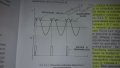
The graph shows that when the junction that needs to be synchronised gets to the value of a DC junction that is used for refrence (point A on the graph) the syncronising circuit makes a brief signal.20181204_205538.jpg
 

Attachments

MrChips

Joined Oct 2, 2009
34,809
You are misinterpreting the information shown.
It has nothing to do with whether or not the op-amp conducts current.
What you see is a design objective. You want the circuit to produce a short pulse at the instant that the voltage threshold is exceeded. How you design the circuit has nothing to do with an op-amp. Normally one would use a voltage comparator followed by a monostable multivibrator. In past instruments, a tunnel diode was also used.
 

Thread Starter

nikola1912

Joined Oct 25, 2017
24
You are misinterpreting the information shown.
It has nothing to do with whether or not the op-amp conducts current.
What you see is a design objective. You want the circuit to produce a short pulse at the instant that the voltage threshold is exceeded. How you design the circuit has nothing to do with an op-amp. Normally one would use a voltage comparator followed by a monostable multivibrator. In past instruments, a tunnel diode was also used.
It is quite important for me to understand how this specific circuit works. And you are right. In the picture where it says "NAPONSKI KOMPARATOR" above the op amp, that means voltage comparator and the box to the right is a generator of short impulses (translated from my language, idk if that's acctualy what it's called). In my book it says that when the voltage on the inverting input is lower than the voltage on the noninverting input the voltage devider is in positive saturation. That is what I don't understand. How and why?
 

Papabravo

Joined Feb 24, 2006
22,082
The comparator has two analog inputs, and one digital output. It is a high gain amplifier that responds to the difference in voltage between the two inputs. When the input is less than the threshold, the output is low. When the input exceeds the threshold by a few millivolts, that difference is multiplied by a factor of say 10,000 which drives the output to the positive rail. this behavior is also referred to as saturation.
 

Thread Starter

nikola1912

Joined Oct 25, 2017
24
The comparator has two analog inputs, and one digital output. It is a high gain amplifier that responds to the difference in voltage between the two inputs. When the input is less than the threshold, the output is low. When the input exceeds the threshold by a few millivolts, that difference is multiplied by a factor of say 10,000 which drives the output to the positive rail. this behavior is also referred to as saturation.
What is the threshold?
 
Top