optocoupler isolation false pulse from piezoelectric

Thread Starter

fibertech

Joined Oct 29, 2024
13
The good news is that there has already been a vast amount of study done on how to prevent outside voltage transients from causing incorrect functioning of electronic circuits. The basic problem has been around for as long as circuits, only the specific source of the problem is new. So there is a great deal of knowledge available, but probably not much on the "cartoon channel", where fake information seems to be common.
Do you know where the bad actors are applying the high voltage to the system?? That will be a starting point towards the solution.
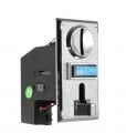
they will apply a surge of voltage using piezoelectric lighter to the coin acceptor .
 

MisterBill2

Joined Jan 23, 2018
27,584
OK, so if the voltage is applied to the coin acceptor slot, or is it a system where the coin is placed in an opening and then slides in? In either case, a solid connection from that metal portion directly to the mains supply safety ground wire should provide a bypass for the voltage pulse.
Is it possible to provide a photo of the coin slot? Both outside and inside? That would provide a lot of useful information toward deciding a method of solving the problem.
 

Thread Starter

fibertech

Joined Oct 29, 2024
13
OK, so if the voltage is applied to the coin acceptor slot, or is it a system where the coin is placed in an opening and then slides in? In either case, a solid connection from that metal portion directly to the mains supply safety ground wire should provide a bypass for the voltage pulse.
Is it possible to provide a photo of the coin slot? Both outside and inside? That would provide a lot of useful information toward deciding a method of solving the problem.
they will touch the body of the coin acceptor with the piezoelectric lighter
 

Attachments

MisterBill2

Joined Jan 23, 2018
27,584
OK, now I understand the situation better. Certainly when the design was made more compact, the designers never considered any problem like you have. And all of the sensitive electronics parts are very close to that front portion, as well. Is that front part metal, or is it plastic? And where are the connections to the electronic portion?? It does not look like there is any way to modify the electronics portion.
Are you able to add anything to the front panel of the vending machine?? I am thinking of a narrow metal trim that can be tied to a good ground connection inside the machine.
One possible simple fix might be wrapping the part inside the machine with aluminum foil with a bare grounded wire around that. Nothing would show outside.
 

Thread Starter

fibertech

Joined Oct 29, 2024
13
If you're getting false pulses when using an optocoupler for isolation with a piezoelectric sensor, it could be due to noise or spurious signals from the piezo element. Piezoelectric sensors can produce high-frequency noise that may trigger the optocoupler unintentionally, especially if the circuit isn't adequately filtered. Adding a small capacitor across the piezoelectric sensor or implementing a low-pass filter in the circuit could help dampen these unwanted signals. Also, ensure that your wiring is well-shielded, as piezo elements are sensitive to external vibrations and electromagnetic interference, which could also cause false triggering.
its not piezoelectric sensor. it's piezoelectric from cigarette lighter use to have a credit in vending machine without inserting coin. i also tried to add rc filter but failed to isolate the surge.
 

Thread Starter

fibertech

Joined Oct 29, 2024
13
OK, now I understand the situation better. Certainly when the design was made more compact, the designers never considered any problem like you have. And all of the sensitive electronics parts are very close to that front portion, as well. Is that front part metal, or is it plastic? And where are the connections to the electronic portion?? It does not look like there is any way to modify the electronics portion.
Are you able to add anything to the front panel of the vending machine?? I am thinking of a narrow metal trim that can be tied to a good ground connection inside the machine.
One possible simple fix might be wrapping the part inside the machine with aluminum foil with a bare grounded wire around that. Nothing would show outside.
i use plywood enclosure. the connection between the electronic board & coin acceptor is the wiring to power the coin acceptor & signal wire to the optocoupler of board.
 

MisterBill2

Joined Jan 23, 2018
27,584
OK, now another question: Is any portion of the coin accepter made of metal?? Or is it all plastic??
Could we get a side view of the acceptor, and now I am thinking that there must be two parts, one that goes from the front of the panel and another part that it connects to behind the panel.

And now I have another idea, which is to create a circuit that senses that power spike and sets off an alarm bell, and then does a reset so that the signal is not sent. And the bad actor can be recognized and their business not allowed.
Sensing the power spike should be easy to do, and it would not require any changes to the coin accepter device.
IT might work even better to have the sensor switch off the machine power for a minute each time they sent a shock to the machine. Then you could accuse them of breaking the machine, and demand a payment!
 
Top