Opto interrupter circuit

Thread Starter

camerart

Joined Feb 25, 2013
3,724
Hi,

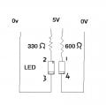
I am about to use photo interrupters for use in quadrature encoders, to control motors.

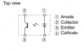
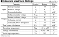
I am going to use Sharp GP1S096HCZOF interrupters for this. Can anyone help me, to use the correct components for this as they will be built into sealed containers, and reliability is hoped for. The outputs will be connected to PIC pins for the control.

Cheers, Camerart.
 

MaxHeadRoom

Joined Jul 18, 2013
28,619
You need two for quadrature pulses, you can also get dual opto's and use for this purpose however you have to use the slotted disc with exact amount of pulses dependent on the diameter of the disc and distance between the two opto's.
This also governs your resolution.
The ones you have can have a 220/330Ω on the diode side and 470/1kΩ on the transistor side.
Max.
 

Thread Starter

camerart

Joined Feb 25, 2013
3,724
Are you sure that you want to make your own quadrature encoder?

You could buy a shaft encoder and couple it to your motor through gears, belts or a friction roller.

Another possibility is to put one of these on one of the shafts in your system:

http://uk.rs-online.com/web/p/rotary-encoders/2056881/
Hi Richard,

I'm making them, because for me it is the best option. All of the mechanics and disks are made, I've only got to fix the interrupters and it's done.

C
 

Thread Starter

camerart

Joined Feb 25, 2013
3,724
You need two for quadrature pulses, you can also get dual opto's and use for this purpose however you have to use the slotted disc with exact amount of pulses dependent on the diameter of the disc and distance between the two opto's.
This also governs your resolution.
The ones you have can have a 220/330Ω on the diode side and 470/1kΩ on the transistor side.
Max.
Hi Max,

I'm fitting two to each motor/gearbox. The slotted disk has only 9 dark and 9 light slots, and the two optos are opposite each other on the shaft, giving 3600 after gearing. (It's for counting degrees)

Thanks for your resistor calculations, this answers why I popped the first set of diodes:)

Camerart.
 

Thread Starter

camerart

Joined Feb 25, 2013
3,724
Hi,

Still not working:confused:

Added new interrupter!

When 5v is connected through pins 1 and 4 with a 600Ω resistor in series, I get 5V. With 5V connected through pins 2 and 3 with a 330Ω in series, still 5V at 1 and 4, no change when opto gap is blanked.

Any ideas?
 

Attachments

Last edited:

bertus

Joined Apr 5, 2008
22,270
Hello,

You have the opto the wrong way around.
1 and 4 are the led and 2 and 3 the transistor.


When the led is correctly connected , you should measure between 1.2 and 1.4 volts accross pins 1 and 4.
You might even want to use a 180 or 220 Ohms resistor on the led side.

Bertus
 

Attachments

Last edited:

Thread Starter

camerart

Joined Feb 25, 2013
3,724
Hello,

You have the opto the wrong way around.
1 and 4 are the led and 2 and 3 the transistor.


When the led is correctly connected , you should measure between 1.2 and 1.4 volts accross pins 1 and 4.
You might even want to use a 180 or 220 Ohms resistor on the led side.

Bertus
Hi Bertus,

Embarrassed:rolleyes: they're working now.

I've tried many permutations of connecting, but not that one:)

Could I have have damaged them, do you think I should get fresh ones or will they be ok?

Thanks to you and all that replied.

Cheers, Camerart.
 

Thread Starter

camerart

Joined Feb 25, 2013
3,724
As a matter of interest, I was cutting the beam with a sheet of paper, and soon found it not to be dark enough. I tried different 'mediums' brown electrical tape didn't work, black does.

I had the opto disks made from 300 dot/inch laser film, this didn't work. I made ortho film disks from the laser prints, this works.

Cheers, Camerart.
 

MaxHeadRoom

Joined Jul 18, 2013
28,619
Looks like you were lucky just being under the reverse rating, I suspect you would have seen any irreversible damage by now.
Max.
 

THE_RB

Joined Feb 11, 2008
5,438
As a matter of interest, I was cutting the beam with a sheet of paper, and soon found it not to be dark enough. I tried different 'mediums' brown electrical tape didn't work, black does.

I had the opto disks made from 300 dot/inch laser film, this didn't work. I made ortho film disks from the laser prints, this works.

Cheers, Camerart.
You can reduce the sensitivity by reducing the LED current. just increase the LED series resistor.

It can be a good idea to put a trimpot for the other resistor (photodiode side) to allow you to trim the HI/LO voltages on the output, and to square up the wave duty.

I did that on the quad encoders on this project;
http://www.romanblack.com/onesec/DCmotor_xtal.htm


Using two 20k trimpots. :)
 

Thread Starter

camerart

Joined Feb 25, 2013
3,724
You can reduce the sensitivity by reducing the LED current. just increase the LED series resistor.

It can be a good idea to put a trimpot for the other resistor (photodiode side) to allow you to trim the HI/LO voltages on the output, and to square up the wave duty.

I did that on the quad encoders on this project;
http://www.romanblack.com/onesec/DCmotor_xtal.htm


Using two 20k trimpots. :)
Hi Roman,

I didn't know that! I'll do that, thanks.

C
 
Top