Facebook
 Google
 GitHub
 Linkedin
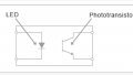
I have a controller with a digital input and digital common measuring 3vDC. When shorted, it will activate the controller.
Question: I want to create a short by using an opti transistor so that an LED can activate it. Do I need a resistor in the circuit? Is there a general opti transistor that would work? Thanks!
Question: I want to create a short by using an opti transistor so that an LED can activate it. Do I need a resistor in the circuit? Is there a general opti transistor that would work? Thanks!