Op Amp rectifiers

Thread Starter

Lescollier

Joined Aug 5, 2020
6
Hello
Newbie here. I need a bit of help from someone with a good knowledge of using op amps particularly as rectifiers.
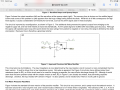
I have a sine Wave of between 0 and lets say 5 v. And a frequency in the region of 180 k hz. The amplitude of the sine wave will change upon detection of an object ( magnetic field ) From this sine wave I want to derive a D.C. voltage in proportion to the p to p value of the sine wave.
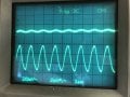
I am trying to use a precision instrument rectifier and then some smoothing to produce the D.C. signal but I am having trouble. the op amp does not appear to produce what it should at this high a frequency I think it’s not up to the job using a LM324N

any help gratefully received

regards

LesC
 

OBW0549

Joined Mar 2, 2015
3,566
A couple of questions:

1) What supply voltage(s) do you have available? A single, +5V supply is a lot harder to work within than ±12V, for example.

2) Do you rreally, really, REALLY need precision for this application? Life will be a LOT easier than if you don't.

3) What op amps besides the LM324 do you have available? For a precision rectifier circuit you should be using something at least 10X as fast as an LM324.

4) Could you please post a schematic diagram of what you've tried so far? Verbal descriptions of circuits are pretty much useless.
 

Thread Starter

Lescollier

Joined Aug 5, 2020
6
Welcome to AAC!
Help us help you by including a schematic when discussing circuits.

If you go outside of the LM324's common mode input range, the output will invert.

What is the opamp gain?
I had the gain set to a 100 at one stage and I think it did what you suggested I.e. inverted . I am now back on unity gain but the output is very small.
A couple of questions:

1) What supply voltage(s) do you have available? A single, +5V supply is a lot harder to work within than ±12V, for example.

2) Do you rreally, really, REALLY need precision for this application? Life will be a LOT easier than if you don't.

3) What op amps besides the LM324 do you have available? For a precision rectifier circuit you should be using something at least 10X as fast as an LM324.

4) Could you please post a schematic diagram of what you've tried so far? Verbal descriptions of circuits are pretty much useless.
The supply is 12 v via Set of car batteries.

I am going to feed the dc signal to the analogue input of a micro. So at the end of the day I am expecting to get a number that represents the voltage. Accuracy can be sacrificed, what I really need is to be able to observe the number and if it changes too much alarm on that.

I have no other amps available at the moment but happy to purchase. Ideally single sided with respect to power supply I.e ground And +12 v

I have used the std 1/2 wave circuit see attached and see scope trace top trace = output. Lower trace = input
 

Attachments

Thread Starter

Lescollier

Joined Aug 5, 2020
6
I am intending To take a sample and Compare it to the last sample taken. I am looking for drift in the sample ( which represents distance ) If the drift becomes to great I will alarm. I am trying to get a higher resolution but struggling to get anything working at the moment .
 

OBW0549

Joined Mar 2, 2015
3,566
Precision rectifier circuits place a great demand on an op amp's speed, both gain-bandidth product and slew rate limit. For a signal frequency of 180 kHz, a precision rectifier circuit would need a VERY fast op amp, perhaps 100X as fast as an LM324.

If I were tackling this design, I'd probably start by amplifying the input signal up to a reasonable level around the point where you want to trigger some operation in your micro, say a few hundred mV peak-to-peak. Then I'd rectify this signal using a passive rectifier with Schottky diodes (like 1N5819 or something like that) and a smoothing capacitor, then amplify the resulting DC signal to a level that can be measured with your micro's ADC.

You can check out this thread for some ideas on op amps.
 

Thread Starter

Lescollier

Joined Aug 5, 2020
6
Precision rectifier circuits place a great demand on an op amp's speed, both gain-bandidth product and slew rate limit. For a signal frequency of 180 kHz, a precision rectifier circuit would need a VERY fast op amp, perhaps 100X as fast as an LM324.

If I were tackling this design, I'd probably start by amplifying the input signal up to a reasonable level around the point where you want to trigger some operation in your micro, say a few hundred mV peak-to-peak. Then I'd rectify this signal using a passive rectifier with Schottky diodes (like 1N5819 or something like that) and a smoothing capacitor, then amplify the resulting DC signal to a level that can be measured with your micro's ADC.

You can check out this thread for some ideas on op amps.
Hi so the first op amp that takes the signal needs to be a fast one ( frequency 175k - 200k ) I then rectify to dc the second op
Amp can then be almost any general purpose op amp as signal is now not time critical. The second option amp is amplifying the signal ready for the micro .
is this correct / what you intended ?
 

OBW0549

Joined Mar 2, 2015
3,566
Hi so the first op amp that takes the signal needs to be a fast one ( frequency 175k - 200k ) I then rectify to dc the second op Amp can then be almost any general purpose op amp as signal is now not time critical. The second option amp is amplifying the signal ready for the micro .
is this correct / what you intended ?
That's correct.
 

Audioguru again

Joined Oct 21, 2019
6,673
The datasheet for the lousy old LM324 quad and LM358 dual opamps show that at high output levels its output converts the sinewave into a triangle waveform and its maximum output level drops above only 5kHz.
At low levels its max gain at 180kHz is only 2 or 3 times with horrible distortion.
It has crossover distortion and a lot of hiss noise.

A modern OPA134 single, OPA2134 dual and OPA4134 quad audio opamp has low noise and low distortion and works perfectly up to 250kHz but the maximum gain at 180kHz is about 50 times. Faster opamps are availanle.
 

crutschow

Joined Mar 14, 2008
34,281
The computer simulation I did however suggests 0 through to 4 volts AC i.e -4 to +4 Peek to Peek
That's of little help.
How close to 0V?
What accuracy?
To do a proper design you always need tolerances on all the specs (which can be one of the harder parts of the design to specify).
 

Thread Starter

Lescollier

Joined Aug 5, 2020
6
That's of little help.
How close to 0V?
What accuracy?
To do a proper design you always need tolerances on all the specs (which can be one of the harder parts of the design to specify).
Hi I wish I could be more exact but at this stage it’s about as close as I can get.

sorry

LesC
 
Top