op amp - offset and gain

Thread Starter

and1_hotsauce

Joined Apr 6, 2011
19
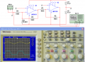
I am to design a ckt. with input range 100mV to 400mV and output range -10v to 10V

and it goes on to say include points in both ckts. to allow for adjustable setting of the offset and gain in each case. Aim for an adjustment range of +-1V for offset and gain.

The circuit I've drawn is given below. In the lecture notes it has -15V going into pin 2. Vin is the 100mV-400mV supplied by a function generator.

My questions are:
Where do I connect the pots?
What does this -15V do? Can i connect 12v? 6v? etc?


Audioguru

Joined Dec 20, 2007
11,248
Your opamp does not have a power supply so it will not do anything.
When you show its power supply voltages then we can show you what the -15V at R1 does to its output voltage.

Your signal generator resistance must be shown since it is in series with R2.
 

Thread Starter

and1_hotsauce

Joined Apr 6, 2011
19
thanks for reply. The op amps are LM741, so I assume Vcc and -Vcc will be +15v and -15v respectively

Lab sheet says to set the signal generator to High Impedance
 

Audioguru

Joined Dec 20, 2007
11,248
The -15V at R1 causes a DC offset at the input which the opamp inverts. So when the 34k pot is at 34k then the output of ther opamp is as positive as it can go which is about +13VDC.
When the 34k pot is zero ohms then the output of the opamp is 0VDC.

The signal is attenuated by the high output impedance of the signal generator and R2 so the output signal level is very small. It is much smaller when the 34k pot is at zero ohms.
 

hgmjr

Joined Jan 28, 2005
9,027
Have you made any progress toward your solution? Do you have any new information to provide concerning your circuit?

hgmjr
 

Thread Starter

and1_hotsauce

Joined Apr 6, 2011
19
I have modelled the circuit using multisim. It is given below. Screenshots of outputs are also given. I am expecting an output of -10V to 10V on the osclliscope but I'm getting some weird values.
note: I put 400mV and 110mV on function generator to account for internal resistance of the generator


t_n_k

Joined Mar 6, 2009
5,455
Your circuit values are OK and it should work in principle. Probably an error in the simulation set-up. I have no experience with Multisim.
 

Audioguru

Joined Dec 20, 2007
11,248
The (-) input of the oscilloscope should be connected to ground, not pin 2 of the first opamp.
Why is the input signal at only 1Hz? Try 1000Hz (1kHz).

The signal generator has an output impedance of zero ohms so the first opamp will have a gain of 34k/510= 66.7 times. The 0.4V pk signal plus the 0.11V offset will be ampified so high that both opamps will have their outputs saturated.
 

JMJ

Joined Apr 14, 2011
3
I'm having the same issues with this particular circuit too.

Same inputs +100mV to +400mV and output -10V to +10V with the y=mx+b gain and offset formula Vout=66.67Vin-16.67

I'm using a Signal Generator" Sawtooth Waveform, High Z, Amp= +300mV, Offset=+100mV

I have a trim pot on the Gain and Offset but the output waveform:
- Seems to Clip
- Is not -10V to +10V output
- Seems to clip when adjusting an offset trim
- Seems to increase and decrease when adjusting gain trim
 

Audioguru

Joined Dec 20, 2007
11,248
Where do you set the function generator to Hi-Z?
How high is the impedance of "hi-Z"?
Don't you know that if you add a DC input offset voltage then the opamp will amplify it and crash its output against a power supply rail which is clipping?
 

Audioguru

Joined Dec 20, 2007
11,248
Adding a resistor from V+ to GND only drains current from the V+ supply and does not affect the opamp.

Don't you know that for the output to be symmetrical then you must adjust the DC current in R2 (by adjusting the DC offset voltage of the signal generator) to produce exactly the same current as is in R1 but of the opposite polarity so they cancel?

Don't you know that since an opamp has such a very high internal gain then when it is not clipping it makes the pin 2 voltage exactly the same as the pin 3 voltage which is 0V?

R1 has 15V across it and is 30.6k ohms. Then its current is -(15/30.6k)= -0.49mA.
You want R2 to have +0.49mA so the DC offset voltage of the signal generator must be +(510 x 0.49mA)= +0.25VDC.
 

Adjuster

Joined Dec 26, 2010
2,148
The power supply "batteries" in the schematics seem to have positive and negative values as well as positive and negative orientations. Is this correct?
 

Audioguru

Joined Dec 20, 2007
11,248
The power supply is positive 15V and negative 15V. Two 15V batteries can be used.
The two power supplies or batteries join together at 0V (the ground of the circuit).
 
Top