Op Amp integrator problem

Thread Starter

aminhosseiny

Joined Sep 4, 2015
3
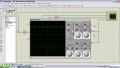
I made this op-amp integrator to have sharp edges triangular pulse in out out but this gives me something corrupted. Please help me to resolve my problem. The capacitor is not necessary so we could easily ignore it.


Attachments

crutschow

Joined Mar 14, 2008
34,201
What are the supply voltages?
The output of U3B is going directly to the summing junction of U1B, which won't work properly.
A summing junction sums currents, not voltages, thus you need a resistor in series with the U3B output to convert its voltage to a current at the summing junction.
 

cowades

Joined Feb 6, 2012
11
Here's another way to think about what crutschow said: the equation for an integrator is -1/RC where R is the input resistor and C is the feedback capacitor. You've got no input resistor (R=0) so the equation looks a lot like negative infinity.
 

crutschow

Joined Mar 14, 2008
34,201
Well thanks. what will happen to R5? should I remove it? if not I just need to add a new resistor for U3B output?
I see no purpose for R5 or R7 so they both can be eliminated.
The resistor at U3B's output (U1A's input) is to provide the resistor to make U1A into a integrator with an RC time-constant, the new resistor being the R (assuming that's what you want).

You seem not to understand how an op amp integrator works. Perhaps you should read up on that.
 
Top