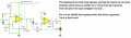
The schematic is a circuit that pulses an LED with the seconds movement of a 1.5 volt battery clock magnetic coil. The TL082 works but the LF353 stays lit continuously. I want the LF353 to work so what is wrong with my schematic?
I'm not sure if both opamps don't work in each chip but I tried different LF353s and it failed to work. I believe miraculously the chip design changed for the worst. I never had problems with them before. It is impractical to require two volts on the non-inverting input. Your conclusion will not explain why the TL 082 works. I tried the lm358 and it worked with about half a milliamp of current and an output of zero volts with no pulse. The tl082 also used half a milliamp of current which is good for several months with AA batteries connected for 9 volts. I already have the prototype working in one of my wall clocks with a tl082. The output of the LF 353 was 6v with a power supply of 7 volts so definitely that can't work because the LED will remain lit. The output of the tl082 was 0 volts with a power supply of 7 volts. This is the voltage when the LED does not blink from the battery powered clock. The coils from the battery powered clock and the amplifier are inductively coupled and in close proximity to each other.
Is it okay to use the TLV272 or LMC 6492. It's more expensive but rail to rail. Can I have the input of the non-inverting or inverting input be at 0 volts compared to ground? Is that the common mode input voltage I'm thinking of?
Is it okay to use the TLV272 or LMC 6492. It's more expensive but rail to rail. Can I have the input of the non-inverting or inverting input be at 0 volts compared to ground? Is that the common mode input voltage I'm thinking of?
Thanks for your suggestion dick. I did try the lm358 and it worked. I am using 9 volts of battery power and I don't have a split supply so I can't use the lf353. Do you have any idea why the tl082 is working good? Since I'm not an engineer I guess that is why I don't understand the data sheet.
Thanks for your suggestion dick. I did try the lm358 and it worked. I am using 9 volts of battery power and I don't have a split supply so I can't use the lf353. Do you have any idea why the tl082 is working good? Since I'm not an engineer I guess that is why I don't understand the data sheet.
 Facebook
 Google
 GitHub
 Linkedin