Facebook
 Google
 GitHub
 Linkedin


Hi,
I need more op amp design help! I'm trying to design a circuit that takes the PWM 0-5V output of my arduino, filters off the PWM frequency (62.5kHZ) and then turn it into a line level output (+/- 0.5V).
This is the circuit I've created:

The first stage is a 3rd order filter designed using this:
http://sim.okawa-denshi.jp/en/Multiple3tool.php
The second stage does the gain and biasing. I used this to work out the values:
http://www.ti.com/lit/an/sloa097/sloa097.pdf
Then I put a non-inverting buffer on the output, in the hope of making it less sensitive to load impedance.
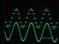
When analysing it directly on the board, the output looks great!

The notches in the sine wave are fine - it's just because it is sampled at 8-bit.
However whenever anything is connected (audio interface or even just a jack lead), the whole thing gets distorted, with a lot of high frequency interference.

This type of interference seems to vary every time I plug it in and can also change over time. I have also seen some other very strange distortions: entire waveform modulated by +/-0.5V 62.5kHz sine wave (which is the PWM freq) and also strange phasing issues (square wave input becoming pulse wave output, with pulse width dependant on input frequency).
Any ideas why this circuit is going crazy the second I plug something into it? Presumably it has something to do with the impedance of whatever I plug into it? I don't see why just plugging a jack lead in (with nothing on the other end) would cause this.
cheers
Paul
I need more op amp design help! I'm trying to design a circuit that takes the PWM 0-5V output of my arduino, filters off the PWM frequency (62.5kHZ) and then turn it into a line level output (+/- 0.5V).
This is the circuit I've created:
The first stage is a 3rd order filter designed using this:
http://sim.okawa-denshi.jp/en/Multiple3tool.php
The second stage does the gain and biasing. I used this to work out the values:
http://www.ti.com/lit/an/sloa097/sloa097.pdf
Then I put a non-inverting buffer on the output, in the hope of making it less sensitive to load impedance.
When analysing it directly on the board, the output looks great!
The notches in the sine wave are fine - it's just because it is sampled at 8-bit.
However whenever anything is connected (audio interface or even just a jack lead), the whole thing gets distorted, with a lot of high frequency interference.
This type of interference seems to vary every time I plug it in and can also change over time. I have also seen some other very strange distortions: entire waveform modulated by +/-0.5V 62.5kHz sine wave (which is the PWM freq) and also strange phasing issues (square wave input becoming pulse wave output, with pulse width dependant on input frequency).
Any ideas why this circuit is going crazy the second I plug something into it? Presumably it has something to do with the impedance of whatever I plug into it? I don't see why just plugging a jack lead in (with nothing on the other end) would cause this.
cheers
Paul