OP-Amp Comparator malfunctioning

Thread Starter

Hamza Mustafa

Joined Mar 1, 2018
12
Hey !!
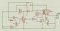
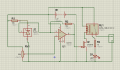
I have an op-amp comparator circuit which in a battery charge controller. As the battery voltages reaches the set point the comparator output becomes unstable and goes high/low until the potentiometer is manually varied.
 

Sensacell

Joined Jun 19, 2012
3,432
Needs some hysteresis. (positive feedback)
Replace C1 with a diode, use a better opamp than the ancient, crippled 741.
 

Thread Starter

Hamza Mustafa

Joined Mar 1, 2018
12
Needs some hysteresis. (positive feedback)
Replace C1 with a diode, use a better opamp than the ancient, crippled 741.
I tried the hystresis but did not work. 1k feedback resistor was added. I have added the C1 capacitor because the relay starts buzzing near the set point, so just to smooth the voltage and lower down the noise.
 

be80be

Joined Jul 5, 2008
2,072
Why is there R3 and R4 And R6 none of that is needed but you need a diode as said across the coil of the relay and a resistor on the base to shut the transistor off faster.
 

Thread Starter

Hamza Mustafa

Joined Mar 1, 2018
12
Why is there R3 and R4 And R6 none of that is needed but you need a diode as said across the coil of the relay and a resistor on the base to shut the transistor off faster.
So you are suggesting the capacitor useless, and there is a resistor on the base of the transistor
 

LesJones

Joined Jan 8, 2017
4,174
If the OP amp was behaving as a perfect OP amp then I don't see how it's output can ever go low. You are comparing the battery voltage with a fraction of the battery voltage so the inverting input of the OP amp will ALWAYS be less than the non inverting input. You need something to provide a fixed refference voltage to compare the battery volyage to. You are trying to compare the battery voltage with the battery voltage which makes no sense. As others have said chose a more recent op amp. (The 741 design is over 50 years old.)

Les.
 

Thread Starter

Hamza Mustafa

Joined Mar 1, 2018
12
@LesJones how do u suggest to provide a fixed reference, since it is a charge controller I can only use the battery voltage.
Why is there R3 and R4 And R6 none of that is needed but you need a diode as said across the coil of the relay and a resistor on the base to shut the transistor off faster.
Removed the excess resistors but still problem persisting.
 

AnalogKid

Joined Aug 1, 2013
10,987
Besides the lack of hysteresis, which would solve the problem you describe, there is another problem - the circuit will not work as shown.

The 741 is old, but that is not the problem.
Its input common mode voltage range does not include either rail, but that is not the problem.
The output cannot swing low enough to turn off the relay, but that is not the problem.
The very large capacitor across the relay coil is not the problem.
Other opamps of the same vintage would work better in this type of application, but *none* of them will work in this circuit.

Yes, the 741 is configured as a comparator, but it is comparing the battery to itself, not to an independent voltage reference. As such, the comparator never will "trip".

ak
 
Last edited:

ebp

Joined Feb 8, 2018
2,332
I suggest manually writing the equations for the voltages at the inverting and non-inverting inputs. I think that will show you why the circuit will not work as intended. You could simplify the circuit so the potentiometer and the resistors in series with it were replaced with just two resistors to simplify the equations. Assume that no current flows into or out of the 741 inputs.
 

Thread Starter

Hamza Mustafa

Joined Mar 1, 2018
12
I have used the TL431 with fixed Vref=2.5V at pin 3, also added hystresis with a 10K feedback resistor. A little improvement but still the problem remains adament.
 

LesJones

Joined Jan 8, 2017
4,174
I assume that R2 is intended to add some hysteresis to the circuit. This will not work very well as the source resistance of the 2.5 volts refference from the TL431 is very low. Try adding a resistor (Say 100 ohms.) between U2 pin 3 and pin 3 of the 741. (The end of R2 still connected directly to pin 3 of the 741). The 2N3819 is a bad choice of device to drive the relay as it works in depletion mode. (The gate needs to be taken negative of the source to turn it off. ) I would suggest using a mosfet (Which works in enhansment mode.) such as a 2N7000.

Les.
 

AnalogKid

Joined Aug 1, 2013
10,987
The hysteresis is not working because the output impedance of U2 is too low.

1. Add a 10K resistor between U2pin1 and U3pin1.
2. Increase R2 to 100K

HEY GUYS - Q1 is a JFET, not a MOSFET. That is a problem.

OK, it's not a JFET, it is a BJT. STILL a problem.

The output of an LM741 cannot swing down to GND (its negative rail power connection), so the output transistor never turns off. And, there must be a resistor in series with the base to limit the base current.

ak
 
Top